
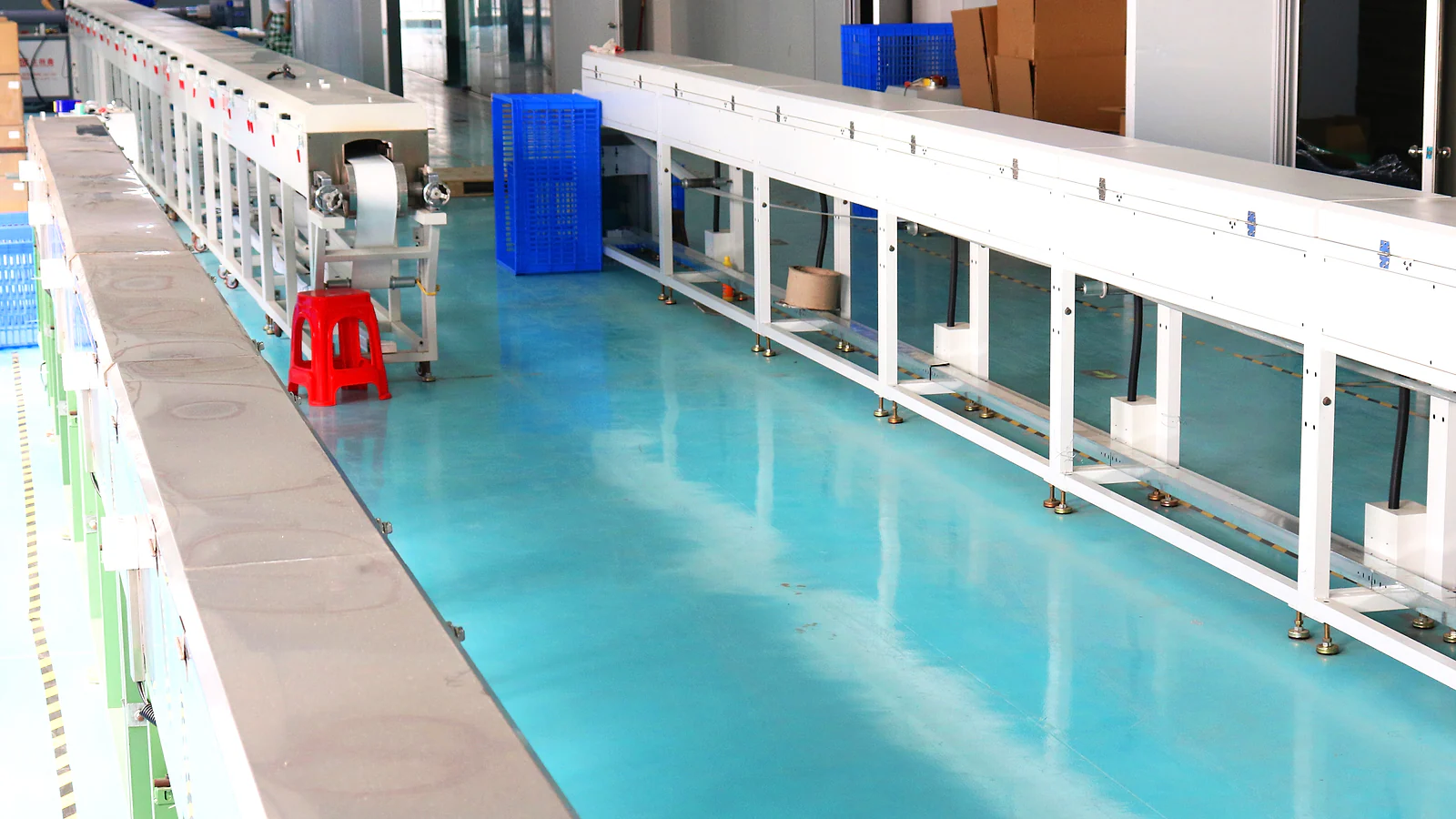
The silicone extrusion process forms a continuous profile by preparing a silicone compound, feeding it through an extruder, shaping it through a die and curing the profile so it retains the required cross-section. For a custom LED lighting profile, however, manufacturing does not begin at the machine. It begins with the installation, LED strip, light direction, bending route and assembly details that the cross-section must support.
Quick answer: A custom silicone lighting profile normally moves through requirement review, cross-section definition, material and colour review, tooling, trial extrusion and curing, sample inspection, approval and production preparation. The die creates the continuous shape, but the drawing and approved sample define what the profile is expected to do in the finished lighting assembly.
What Is Silicone Extrusion?
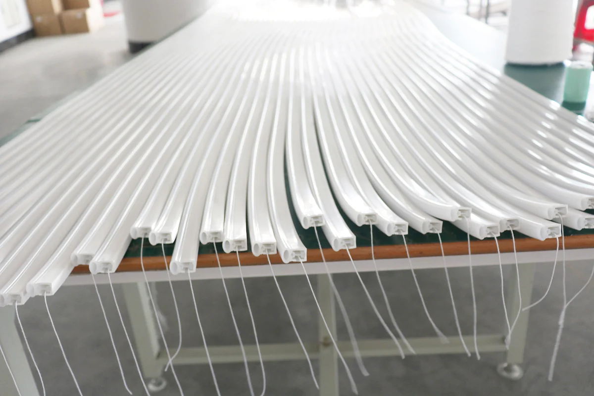
Silicone extrusion is a continuous forming process. Prepared uncured silicone is fed into an extruder, moved under controlled pressure through a die and produced as a continuous profile. The profile then passes through the applicable curing stage before it is cooled, handled, cut, coiled or prepared for further assembly.
The die opening establishes the basic cross-section, but it is not a simple copy of the final drawing. Material flow and the curing process affect the finished result, so tooling and production settings are developed around the selected material and target profile.
Extrusion is suited to products that maintain a consistent cross-section along their length, including tubes, sleeves, channels, cords and project-specific profiles. Features that change from one point to another, such as a local cable exit or end closure, are normally handled as separate fabrication or assembly details rather than by the continuous die alone.
Why LED Lighting Profiles Need an Application-First Review
A generic extrusion can be described by its outer dimensions. An LED lighting profile needs more information because the internal geometry affects both assembly and light appearance.
Before tooling, review:
- the available installation space and mounting interface;
- the LED strip width, component height and intended position;
- the visible or diffusing surface;
- the required light direction after installation;
- the route and permitted bending direction;
- cable exits, end details, connectors and joints;
- cut lengths, continuous lengths, reels or assembled formats;
- the sample and acceptance requirements.
The Custom Silicone Extrusion page shows how a drawing, sketch or physical sample can provide the starting basis for this review.
The Silicone Extrusion Process Step by Step
1. Review the Drawing, Sample or Installation Requirement
The first step is to identify what is fixed and what can change. A cross-section drawing is useful, but a physical sample or installation sketch can also establish the starting point.
For an LED profile, dimensions should be accompanied by the intended function. Mark the light-emitting surface, strip position, mounting points, bending route and cable direction. A dimension without its mating component or installation reference can be interpreted incorrectly.
2. Define the Profile Cross-Section
The cross-section turns the project information into a manufacturable profile direction. It defines the outer geometry, internal channel, walls, openings, interfaces and visible surfaces.
Important questions include:
- Does the strip fit without pressing on components?
- Is there room for the intended insertion or assembly method?
- Which surface should transmit or diffuse light?
- Does the profile sit, clip, insert or bond into another part?
- Where can the cable and connection hardware be placed?
- Which plane must the finished profile follow when it bends?
Avoid adding thin decorative details or internal features without a clear function. Every feature should support fit, light, bending, mounting or assembly.
3. Review the Silicone Requirement
The material must be selected for the actual product and application. Colour, translucency, visible appearance, mechanical behaviour, curing system and any required material or market documentation should be discussed for the quoted profile.
Do not assume that one general silicone description applies to every profile. The appropriate material basis and available documentation should be confirmed against the selected product and target market. The Material & Compliance Documents page explains how supplier, material and product documents are reviewed without representing them as universal AlisterTech certifications.
4. Design and Produce the Extrusion Tooling
The die shapes the continuous profile as the silicone exits the extruder. Tooling is developed from the reviewed cross-section and selected material process, with allowance for how the compound flows and changes during curing.
Tooling approval should not be confused with final product approval. The first tool provides the basis for a trial; the resulting extruded sample must still be measured and reviewed. Complex or asymmetric channels may require adjustment before the sample matches the approved drawing and requirements.
5. Prepare the Material and Run the Trial Extrusion
The selected silicone is prepared according to the applicable manufacturing process and fed into the extrusion line. The extruder moves the material through the die to form the continuous profile.
During a trial, the operator monitors the profile as it exits the tooling. The goal is not only to produce the shape, but to establish stable conditions that can hold the required cross-section along the reviewed length.
6. Cure and Stabilize the Profile
Freshly extruded silicone must be cured using the process selected for the material and production line. Curing stabilizes the profile and develops the properties expected from the chosen compound.
The curing method, temperature, pressure and speed are process-specific. They should not be copied from a general article or another product. Only the approved material and manufacturing instructions should control the production settings.
7. Inspect the Trial Profile
After curing and cooling, the sample can be checked against the development drawing and intended assembly. Inspection may include:
- outer dimensions and internal channel dimensions;
- visible surface condition;
- consistency along the reviewed sample;
- strip insertion and internal fit;
- emitting-surface orientation;
- bending direction and route;
- end, connector and cable-exit details;
- assembled light appearance where required.
A dimensional check alone does not confirm the finished lighting result. Conversely, an attractive illuminated sample does not replace the required dimensional and assembly review.
8. Build and Review the Lighting Sample
Where the profile will house an LED strip, assemble a representative sample using the proposed strip, connection and end details. Review the sample from the intended viewing position and under the relevant operating condition.
Confirm what the sample is intended to approve. This may include profile fit, light direction, visible diffusion, cable routing or assembly method. Record any point that remains outside the sample scope.
9. Confirm the Production Requirements
Before production, confirm the identified drawing, sample and agreed project information. If the LED strip, cross-section, material appearance, cable exit or other critical detail changes, the approval basis should be reviewed again.
The Quality Control page describes how inspection scope can be matched to the quoted product rather than treated as a universal test package.
Process Stage and Project Information
| Process stage | Information from the project | Output for the next step |
|---|---|---|
| Requirement review | Drawing, sample, installation and quantity | Confirmed project requirements |
| Cross-section definition | Dimensions, strip, light and mounting interfaces | Reviewed profile drawing |
| Material review | Appearance, environment and document scope | Selected material basis for quotation or trial |
| Tooling | Approved profile direction | Extrusion die for sample development |
| Trial extrusion and curing | Tooling and selected process | Physical profile sample |
| Profile and assembly review | Sample, strip and connection details | Recorded feedback and required corrections |
| Production preparation | Approved drawing, sample and order scope | Confirmed basis for the quoted production run |
This sequence reduces ambiguity, but it does not mean every project requires the same number of trials. The profile geometry and approval requirements determine the appropriate development path.
Silicone Extrusion vs Silicone Moulding
Extrusion and moulding serve different shape requirements.
| Question | Extrusion | Moulding |
|---|---|---|
| Primary geometry | Continuous cross-section | Discrete part formed in a cavity |
| Typical output | Tubes, channels, sleeves and long profiles | End parts, closures and shaped components |
| Length | Produced continuously, then cut or coiled | Defined by the moulded part |
| Local features | Usually added through secondary fabrication or assembly | Can be formed into the individual part when designed into the mould |
| LED-lighting role | Main silicone profile or housing | End details or project-specific components where applicable |
Some lighting assemblies may use both processes. The correct route depends on the component geometry, material and required assembly rather than on one process being universally superior.
What Can Change the Difficulty of a Custom Profile?
Asymmetric Geometry
A profile with uneven wall relationships or an off-centre internal channel may behave differently during forming and curing. The trial sample shows whether the tooling and process produce the intended section consistently.
Thin Walls and Narrow Internal Channels
Features that leave little manufacturing or assembly margin require careful review. The strip and its components must fit without relying on nominal dimensions alone.
Light-Diffusing Surfaces
The visible light surface is both an optical and material feature. Colour and translucency should be evaluated with the intended LED strip and viewing position, not only from an unlit profile sample.
Bending Requirements
The profile route and bending plane should be known before the cross-section is finalized. A flexible material does not mean the assembled product can bend in every direction.
Connection and End Details
Cable exits, end closures and connectors may require local space that does not appear in the main cross-section. Include these details in the drawing and sample plan.
What Should Be Checked Before Tooling?
Use this checklist before approving a custom profile direction:
- The installation space and mating parts are identified.
- The profile cross-section includes the critical dimensions.
- The exact LED strip or required strip envelope is available.
- The visible surface and light direction are marked.
- The bending route and plane are shown.
- The strip insertion or assembly method is understood.
- Cable exits, connectors and end details are included.
- Material appearance and document requirements are stated.
- Sample acceptance points are defined.
- Estimated production quantity and delivery format are available for quotation.
The Project Preparation page can be used to organize this information before submitting a request.
Common Specification Mistakes
Sending Dimensions Without the Application
A cross-section can fit the stated width and height while failing at the actual mounting interface, bend route or light direction. Include the surrounding detail.
Selecting the Profile Before Confirming the Strip
Nominal strip width does not describe component height, pads, coatings, connectors or cable transitions. Use the proposed strip or a defined dimensional envelope.
Treating the First Trial as Automatic Approval
The first extrusion is a development sample. Measure it, assemble it and document corrections before releasing production.
Approving Only the Unlit Profile
When light appearance matters, review the profile with the intended strip and operating arrangement. The unlit silicone colour alone does not establish the illuminated result.
Leaving Cable Exits Until the End
Connections can change the profile position, end detail and assembly space. Plan them while the cross-section and sample are still under review.
Frequently Asked Questions
What does a silicone extrusion die do?
The die forms the continuous cross-section as prepared silicone passes through the extrusion head. Tooling is developed around the target profile and selected material process, then validated through the extruded sample.
Can a custom silicone profile be made from a physical sample?
Yes. A physical sample can provide a starting reference when a drawing is unavailable. Explain which features must remain, which should change and how the profile works in the installation so a development drawing can be prepared and reviewed.
Does extrusion create the end caps and cable exits?
Extrusion creates the continuous cross-section. Local end closures, cable exits and other features normally require separate fabrication, moulded components or assembly steps, depending on the product design.
When is a custom profile needed?
A custom profile may be appropriate when an existing tube or channel does not fit the installation, strip, light direction, bending route or connection requirement. Review available profiles first, then define the missing function.
What does a sample approve?
Only the criteria recorded for that sample. These may include cross-section, fit, surface, bending, assembly and light appearance. The approval record should identify the drawing, strip, connection and test condition used.
What information is needed for a quotation?
Send the drawing or sample, target dimensions, LED strip information, visible light surface, bending route, application, environment, cable and connection details, required delivery format, sample need and estimated quantity.
Carry the Approved Sample Into the Production Order
Connect the purchase order to the latest drawing or approved sample, housing or assembled-light scope, supply format and inspection requirements. If the strip, internal channel or connection changes after sampling, request another compatibility review rather than assuming the existing approval still applies.
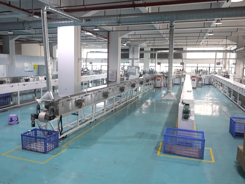
- Project review
- Identify the drawing, sample and fixed installation dimensions
- Tooling and samples
- Confirm the physical sample and development scope
- Assembly scope
- Identify strip integration, cable exits and end details where quoted
- Release
- Confirm the latest reference, format, quantity and agreed checks