
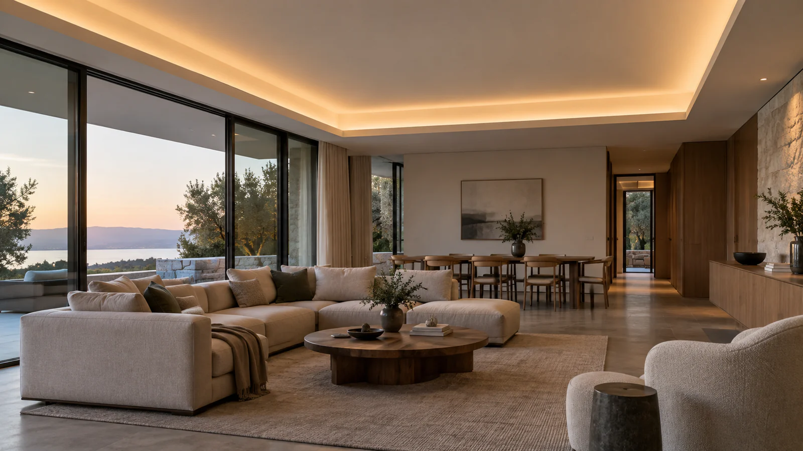
LED cove lighting installation works best when the architectural section and the desired light line are designed together. The strip or finished linear light must be concealed from the normal viewing position while still having enough space for mounting, cable entry, power access and maintenance. A beautiful rendered room does not resolve those construction details; the section drawing and a representative sample do.
Quick answer: Draw the cove section before selecting the light. Keep the source out of the normal sightline, check the reflecting surface and available space, allow access to power and connections, and review the proposed assembly in a representative cove mock-up.
Short answer: LED cove lighting uses a concealed linear source to illuminate a ceiling or wall surface indirectly. Select the lighting assembly after checking the cove opening, mounting space, viewing position and reflected surface. A visible recessed light line is a different detail: its emitting face is seen directly. For either approach, resolve corners, power feeds and service access before installation, then assess the actual strip or finished light in a representative section.
What Is LED Cove Lighting?
Concealed ceiling LED lighting directs light onto an adjacent surface while hiding the source. Ceiling cove LED backlighting describes the indirect effect, not a universal offset, wattage or installation depth. Show the section and the intended view before selecting those details.
What Makes a Cove Light Look Continuous?
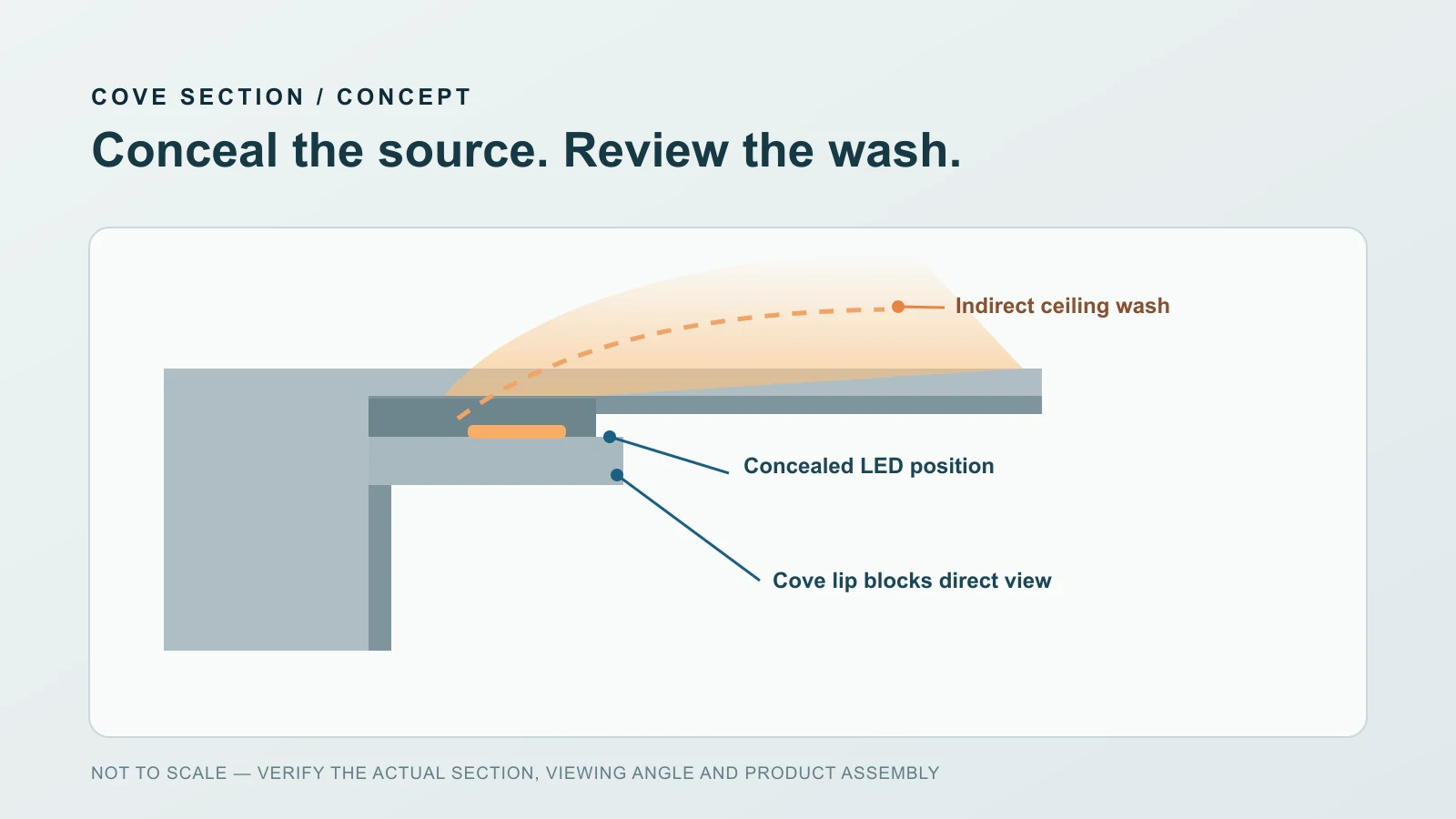
A cove hides the light source behind a lip or recess and lets light wash a nearby ceiling or wall. The viewer sees the illuminated surface, not the individual LED packages. The perceived continuity depends on the light source, diffusion, position within the cove, surface finish and viewing angle.
For an architectural result, check three views at once: the section that shows the concealed source, the view from a normal occupied position, and the surface that receives the light. A detail can look good in section yet expose the LEDs from a staircase or create a hot band on a glossy ceiling.
Step 1: Draw the Section Before Selecting a Strip
Mark the cove depth and opening, the height of the shielding lip, the receiving surface, adjacent finishes, cable path and any access panel. The section should show where the product will actually sit, not merely the intended glow. Add a person-height sightline or other relevant viewing position when the source must remain invisible.
If the ceiling, furniture or wall system is already built, a measured photograph and physical sample may be more useful than an unscaled concept rendering. State which dimensions are fixed and which can still change. That distinction can determine whether a bare strip in a compatible profile, a diffused silicone product or another linear assembly should be reviewed.
Step 2: Define the Light Appearance
Describe what the viewer should see: a soft ceiling wash, a narrow line, a broad luminous band or another deliberate effect. Include the intended light colour, control method and whether the cove is decorative, functional or both. The visible result is affected by the cove geometry and surface reflectance as much as by the LED product.
If the project already specifies a COB or SMD LED strip, provide that model and its operating data. A COB strip can offer a different close-range appearance from individually exposed SMD packages, but neither label alone guarantees a smooth cove. The COB vs SMD guide explains the format difference; diffusion and placement still require testing in the actual detail.
When a visible silicone light line or finished flexible lighting product is preferred, the product family and mounting detail should be reviewed separately. Do not assume an empty silicone sleeve includes LEDs, nor that a complete neon flex is a drop-in replacement for an existing strip.
Step 3: Coordinate the Product With the Cove
Reserve the real height and width for the strip or finished lighting assembly, its mounting channel or clips, diffuser, ends and wiring. Keep the cable exit and any connection body out of the visible area. Confirm the permitted bend direction at corners and any curved coves using the selected product’s drawing.
A continuous-looking cove can still need multiple electrical or mechanical sections. Mark the proposed joins on the architectural drawing so they can be reviewed for light gaps and future access. Avoid hiding a critical termination behind a permanently closed finish without a project-specific access plan.
See Architectural Linear Lighting for the broader application context and Custom Silicone Extrusion when the fixed installation geometry cannot be served by a standard profile.
Compare finished LED neon flex with a separately selected strip and silicone housing. Use the current product catalogues and mounting documents to confirm the quoted assembly.
Step 4: Plan Power, Control and Service Access
Coordinate the supply and controls with the chosen lighting product, the circuit design and the project’s electrical requirements. The product’s voltage, load, run arrangement and control interface must come from its actual documentation. Do not carry a wattage or run length across from a visually similar product.
Provide an accessible route to power equipment and connections. A useful drawing marks where cables enter, where sections terminate, and what can be opened later for inspection or replacement. A qualified electrical professional should verify the final connection and applicable installation requirements. Isolate power before working on the circuit.
For kitchens, bathrooms, exterior edges or other exposed locations, confirm the complete product and connection assembly against the actual environment. A dry-looking render or a silicone exterior does not establish environmental suitability.
Step 5: Test a Representative Cove Section
Build or mock up a short section using the proposed light source, diffuser or profile, shielding lip and receiving surface. Review it from the actual viewing positions under the intended ambient condition. Check whether the source is concealed, the light reaches the planned area and the transition at ends or corners is acceptable.
The sample should answer the project-specific questions: Is the glow too concentrated? Is the cove lip casting an unwanted shadow? Does the ceiling finish reveal individual bright spots? Can the cable exit be concealed without stressing the assembly? Record the accepted configuration before committing to the full ceiling or wall run.
Cove Installation Review Checklist
| Design question | Check on the drawing | Check in the sample |
|---|---|---|
| Concealment | Lip position and occupied sightlines | Source remains hidden from intended views |
| Light line | Source position and receiving surface | Brightness and diffusion appear as intended |
| Physical fit | Assembly envelope, ends and joints | Product can be mounted without distortion |
| Electrical access | Supply, controller, cable and service route | Connections can be made and inspected |
| Continuity | Lengths, corners and joint locations | Transitions are acceptable from the real view |
For a broader project brief, use Project Preparation to gather the installation section, product information and quantities before requesting a configuration review.
Common Cove Lighting Mistakes
Choosing the Product From a Mood Image
An image communicates the desired effect but rarely shows cove dimensions, concealed hardware or access. Pair it with a measured section.
Testing Only a Loose Strip
A loose strip cannot reproduce the shielding lip, diffuser and ceiling reflection. Test the proposed assembly inside a representative cove.
Leaving Driver Access Until After Finishing
Equipment and terminations need a location and a service route. Coordinate them before the ceiling or wall is closed.
Assuming More Power Means a Better Wash
Placement and diffusion often govern the visual result. Use the actual product data and mock-up rather than an arbitrary power increase.
Frequently Asked Questions
Should the LED strip be visible in a cove?
For a concealed indirect effect, the source should normally be hidden from the intended viewing positions. The exact sightline must be tested in the project’s section and sample.
How far should the strip be from the ceiling?
There is no universal distance. The cove geometry, light source, diffuser, receiving surface and desired appearance determine placement. Test the actual detail.
Is COB always better than SMD for cove lighting?
No. COB and SMD are different strip formats. The finished light appearance also depends on source density, diffusion, placement and viewing distance for the selected model.
Can I use LED neon flex in a cove?
It may be suitable when the selected finished product fits the cove, gives the required light direction and has an appropriate mounting and electrical arrangement. Review it against the section rather than assuming a universal substitution.
How do I avoid a visible dark area at a joint?
Mark the joint position, review the selected product’s end details and inspect a representative sample from the real viewing position. The achievable continuity is product- and detail-specific.
What should I send for a cove lighting quotation?
Send the cove section and dimensions, room or application view, desired appearance, existing strip or product reference if any, power and control plan, access constraints, environment and approximate length or quantity.
Coordinate the cove with the wider architectural linear-lighting layout. For shelves and joinery nearby, use the display-case planning guide and cabinet lighting checklist. Review profile manufacturing and assembly before releasing a repeated project detail.