
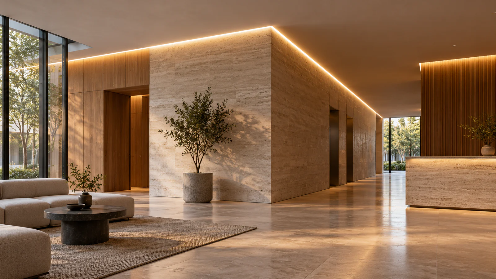
Architectural linear lighting can make a wall, ceiling or transition feel like one deliberate line. That visual simplicity depends on decisions hidden in the construction: where the light sits, what it illuminates, how it turns a corner and where the cable leaves the route. Plan those details before selecting a strip or profile from a photograph.
Quick answer: Start with the lighting purpose and an installation section. Mark the visible light face, available width and depth, route, corners, cable exits and access. Choose an empty silicone housing or a finished light, then review a representative sample before fixing the surrounding detail.
Short answer: This architectural linear lighting guide starts with the route and a representative installation section, rather than a product photograph. Define a recessed visible line, concealed wash or curved contour, then compare the light source, emitting face, housing and mounting together. Check corners, endpoints, cable exits and service locations in the drawing. A continuous visual line may use planned physical sections and accessible joins; review the actual mock-up before approving that appearance.
Decide what should be seen.
Reserve the real installation space.
Resolve corners and endpoints.
Keep access within the design.
1. State What the Line Should Do
A linear detail can define an edge, wash a wall, guide movement or become a visible luminous feature. These purposes change the direction of the light and the way people view it. A source concealed in a cove is judged by the illuminated surface; an exposed line is judged by the face of the product itself. Label the intended effect on the drawing instead of treating every linear run as the same installation.
Identify the main viewing positions. A light that is hidden from the entrance may become directly visible from a nearby seat or upper floor. Glass, polished stone and pale surfaces can reveal an otherwise concealed source through reflection. Mark where the line should remain continuous and where an intentional dark break is acceptable.
The Architectural Linear Lighting application page introduces the setting. This guide focuses on the physical detail that turns the desired line into an installation that can be sampled and quoted.
2. Trace the Full Route, Not Only the Hero View
Draw the line from start to finish on an elevation or reflected ceiling plan. Include every corner, change in level, interruption by a door or column, and transition between wall and ceiling. One attractive perspective image often hides the point where the run begins, the cable enters or a mounting surface changes. Those hidden points determine the real construction.
Separate visual continuity from physical continuity. A long uninterrupted appearance may require multiple manufactured sections with planned joins. The section lengths must account for transport, handling, mounting and access in the actual space. If a curve is part of the design, show its plane and surrounding clearance. A light can bend in one direction but not follow every three-dimensional path drawn in a rendering.
For concealed ceiling edges, the LED cove lighting installation guide looks more closely at the lip, reflected surface and access. A wall-to-ceiling or exposed line adds different concerns: what happens at the transition, whether the emitting face rotates, and how the line meets adjacent finishes.
3. Give the Light Its Real Section
On a section drawing, show the available width and depth after finishes and mounting materials are in place. Add the surrounding edge, the intended emitting surface and the direction of the view. The dimensions that matter are not just the outside of the silicone profile or housing. The selected LED strip, connector, cable exit and any necessary mounting interface must fit within the available volume.
Do not cut a final channel around a nominal catalogue picture. A product may clear the straight portion but conflict with a corner, joint or end fitting. Identify where the installer can hold the profile, what surface supports it and whether the mounting method leaves a visible fastener or gap. If a standard section does not fit the construction, review the section change before the surrounding wall or ceiling is closed.
A silicone tube or profile can form a visible diffusing body around a separately selected strip. It is not itself an illuminated product unless the quoted assembly includes the LED source. When the geometry has to match a particular recess or interface, custom silicone extrusion may be reviewed from a drawing or sample. The desired light direction and internal strip position remain part of that review.
4. Choose the Source and the Appearance Together
A finished LED neon flex may suit a visible flexible line when its section, emitted face, bends and ends match the route. A separate strip and profile assembly can suit a detail where the housing and diffuser are designed into the architecture. Neither option should be selected solely because an isolated image appears smooth or bright.
Check the appearance with the actual source inside the intended diffuser and at the intended viewing distance. LED placement, available depth, surface finish and reflections all affect whether the line looks even. A light can be visually continuous along a straight sample yet reveal a bright point at an end or a dark gap at a joint. Specify the visual acceptance point by point rather than using an unqualified promise of a seamless line.
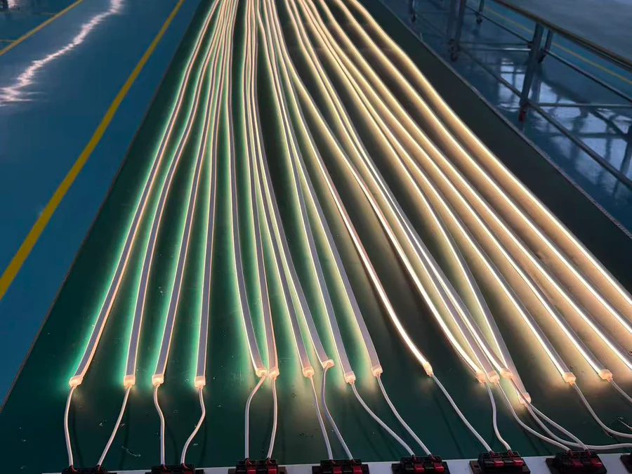
Colour and control decisions should come from the exact selected product and the overall lighting design. If the line must dim or change colour with other luminaires, include the proposed controls in the review. Do not assume that similar-looking samples have the same electrical arrangement or can share one controller.
Compare the Assembly Options
| Requirement | LED Strip + Profile | LED Neon Flex | Custom Silicone Profile | What to Confirm |
|---|---|---|---|---|
| Straight recessed line | Separate source and housing selected together | Review the finished emitting face | Consider when a standard section does not fit | Visible aperture and mounting space |
| Curved visible contour | Strip and housing must both follow the route | Select the permitted bend plane | Review geometry against the fixed interface | Curve, emitting face and transitions |
| Concealed cove or ceiling wash | Review strip position and reflected appearance | Review finished profile visibility | Consider installation-specific concealment | Viewing angle and sample section |
| Continuous appearance with service access | Plan joins and accessible feeds | Review ends, joins and cable exits | Define interfaces before development | Run layout and access to connections |
These are selection routes, not universal compatibility or performance promises. Review COB and SMD LED strips and current product documents against the actual installation.
5. Resolve Corners, Ends and Material Transitions
At every change of direction, ask whether the line should turn continuously, meet at a joint or stop deliberately. A clean corner in a rendering may not reflect the bend plane or end geometry of the real product. Mark the corner detail in plan and section, then check it with the actual profile and light source before approving a repeated run.

Consider what happens when the line crosses a movement joint, changes from plaster to stone or meets a separate ceiling system. The light detail should not be assumed to bridge building movement or carry loads it was not designed to carry. The surrounding construction, not only the flexible product, determines the correct transition. A designed break can look intentional and remain serviceable; an unplanned gap usually looks like a mistake.
Endpoints deserve equal attention. Decide whether the line terminates against a wall, returns around an edge or finishes visibly in space. Show the end cap or cable direction and available recess. The view from the opposite end of a corridor can reveal a termination that is invisible in the main presentation view.
6. Place Cables, Equipment and Access on the Drawing
Show each power entry and any control connection before finalizing the route. Mark where the cable travels through the wall, ceiling or joinery and where the selected equipment can be reached for inspection. A long architectural line may look simple from below but still need several practical connection points. Their positions should be coordinated with the construction rather than decided after finishes are installed.
Keep electrical choices tied to the actual selected product. The length of a run, power arrangement and control equipment must be reviewed using that product’s data and instructions. Avoid carrying a voltage, loading figure or maximum run length from another manufacturer’s guide into this project. If equipment is supplied by another party, state that scope clearly on the drawing.
Access does not require leaving equipment on display. It requires a deliberate route for inspection or replacement that does not damage the architectural finish. Note which trim, panel or section can be removed and whether the cable still has enough room when the product is installed.
7. Review One Representative Mock-Up
Make the sample where the design is hardest, not where the run is easiest. Include a corner, material transition, reflection, termination or tight recess. Put the chosen light and profile into the actual section and view it under the expected ambient lighting from the normal positions. Check the unlit appearance first: body colour, fit, visible fixings and cable exit can be as important as the illuminated result.
Then view the lit line. Look for visible points, abrupt brightness changes, glare at eye level and unexpected reflections. Record any accepted joint or dark break. A scene rendering is valuable for design intent, but the physical mock-up determines whether the selected components and construction produce the intended view.
Photograph the approved detail and mark it on the drawing. If the finish thickness, route or selected LED product changes later, return to that reference and check the affected part again rather than assuming the prior visual approval still applies.
8. What to Send for a Linear-Lighting Review
- Plan or elevation showing the complete light route
- At least one section with finished available space
- Main standing and seated viewing positions
- Visible line, reflected wash or concealed source objective
- Every corner, change of plane and material transition
- Preferred light colour and control requirement
- Mounting surface, end details and cable exits
- Power equipment location and service access
- Existing product reference, sample requirement and estimated quantity
A marked photograph can start the discussion when a detailed drawing is not ready. Identify the measurements that are already fixed and the areas still available for adjustment. That helps distinguish a product recommendation from a construction change.
Common Linear-Lighting Mistakes
Approving Only the Main Perspective
The endpoint and opposite viewpoint often reveal a visible source or awkward termination. Check the whole route.
Confusing the Light Line With a Single Physical Length
Visual continuity can be designed across planned sections; forcing an impractical continuous length is not the goal.
Ignoring the End Fitting in a Narrow Recess
The body may fit while the cable exit or connector does not. Review the assembled end in section.
Leaving Service Access Out of the Detail
A concealed line still needs a way to reach equipment and connections after installation.
Frequently Asked Questions
Does a continuous-looking line need one continuous product length?
No. Planned sections and joints can create a continuous visual result when the transitions are sampled and approved.
Can LED neon flex follow any curved architectural route?
No. The selected model’s bend plane and physical construction must suit the actual curve and mounting detail.
Is a silicone profile the same as a finished light?
Not necessarily. A profile can house a separately selected LED strip. Confirm what the quote includes.
How can visible dots or breaks be evaluated?
Test the actual source and diffuser in a representative section, including an end or joint, from the intended viewing position.
When should a custom profile be considered?
When the available section, mounting interface or intended emitting face cannot be met by a standard format without changing the design.
Choose the Housing Before Finalising the Architectural Detail
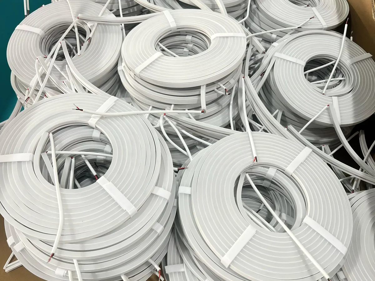
Decide whether you need an empty silicone housing for a separately selected strip or a finished LED Neon Flex assembly. Then check external width and depth, internal strip clearance, mounting support, visible light face and cable access. Silicone housing does not replace a separately designed heat-dissipation arrangement.
- Recessed visible line
- Aperture, outside section and retention
- Curved or raised face
- Projection, strip position and viewing direction
- Round outside form
- Diameter and mounting; do not assume 360-degree output
- Sample review
- Actual strip, light surface and intended viewing distance
Apply the same section-first review to concealed cove lighting, display-case shelves and reflections, and cabinet lighting and cable access. For an integrated flexible light, compare LED Neon Flex families; for a fixed interface that needs a different section, discuss custom silicone profile development.