
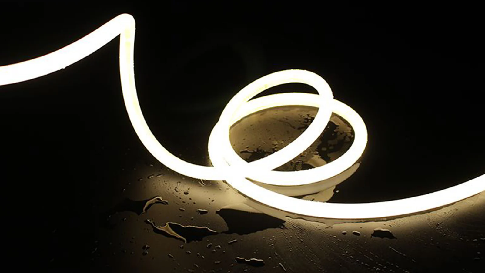
Learning how to install LED neon flex begins with the route drawing, not the first mounting clip. Mark the intended light-facing surface, every curve, the support method and the cable exit before cutting or fixing the product. Those details determine whether the selected neon flex can follow the installation without twisting, overstressing a connection or leaving an unwanted visible gap.
In brief: Confirm the exact product instructions; mark the route and permitted bend plane; plan the mounting and cable access; prepare and test a representative section; then install, connect and inspect the complete light line. Do not transfer bend-radius, cut-point or electrical rules from another model.
Before Installation: Confirm the Product and Route
LED neon flex is a finished light source, not merely an empty silicone profile. Its light-emitting surface, internal strip, conductors, housing, connections and termination method all affect how it can be installed. Start with the selected product drawing and installation instructions. If those documents are unavailable, request them before releasing a cut list or mounting pattern.
The first review should establish:
- the product reference and actual cross-section;
- the permitted bend direction and model-specific minimum bend radius;
- the intended emitting surface and viewer position;
- the allowed cutting and connection method;
- the mounting channel, clips or other specified support;
- the electrical supply and control requirements for that product;
- the installation environment and complete-assembly protection requirements.
A bright product photograph cannot confirm these details. For a choice between bend-plane formats, see our top-bend vs side-bend neon flex guide. This installation article focuses on what happens after the required movement and light direction have been identified.
Step 1: Draw the Route at Installation Scale
Mark the proposed light line on a plan, elevation or photograph. A single view can hide a change in plane, so add a section at the cove, wall edge or other critical transition. Record the visible start and end points, straight runs, curves, corners and the places where the route passes a joint or an obstruction.
Use separate arrows for the light direction and bend direction. They are not interchangeable. A side-emitting surface does not, by itself, tell you which way the finished product may curve. Show where the mounting face sits, then compare the complete path with the arrows in the selected product drawing.
If a route requires a sharp corner or curves in two different planes, stop at the drawing stage. Review a sectional joint, a different product format or a revised route rather than forcing one length into shape.
Step 2: Plan the Mounting Detail
The support should follow the intended route and hold the neon flex without crushing the housing or loading the connections. Match the selected profile to its specified mounting accessory, channel or engineered groove. Check the available recess depth and width, the visibility of clips or channel edges, and the clearance needed for end caps and cable exits.
Do not assume an accessory shown beside a similar-looking product is compatible. The accessories page is a starting point for an interface review; the actual fit must be confirmed against the chosen neon flex and mounting surface.
At curved sections, check that the support follows the approved bend plane. A channel can be visually smooth but still force the product to twist where the route changes direction.
Step 3: Reserve Space for Power and Connections
Locate the power source, controller when applicable, cable route and access point before finalizing the neon flex length. Mark the intended connection positions on the drawing. Keep terminations out of locations where they would be bent or trapped behind inaccessible finishes unless the selected assembly is specifically designed for that arrangement.
Electrical requirements belong to the exact finished product. Confirm the supply voltage, polarity or channel layout, power calculation, permitted run arrangement and any driver or controller requirements from its documentation. A qualified installer should make and test electrical connections under the applicable project requirements. Isolate power before handling conductors.
If the installation is exposed to weather, cleaning water or another demanding environment, review the complete assembly, including cable entry and ends. Silicone appearance alone does not establish an IP rating.
Step 4: Make a Representative Sample
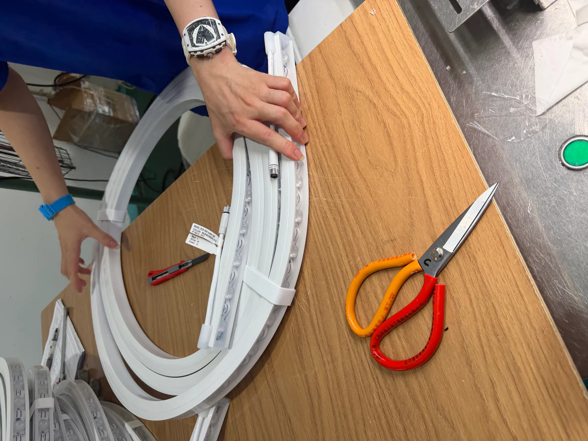
Before a long continuous run or repeated installation, prepare a short representative section with the proposed product, mounting detail and one critical curve. Include a real cable entry or end detail if it influences the visible result. This sample lets the project team check the light line from the intended viewing position rather than judging only a loose coil on a table.
Review the sample with the expected diffuser, adjacent finish and operating condition. Look for visible bright spots, dark sections, distorted housing, strain at an end or light spill that the drawing did not reveal. Record the accepted product reference, orientation and mounting detail before preparing the full quantity.
Step 5: Install and Inspect the Finished Light Line
Follow the selected product’s installation guide and the approved drawing. Confirm the substrate and channel are ready, keep the route free of sharp edges, mount the specified support, and place the neon flex without pulling it through a tight obstruction or twisting it between fixing points. Cut or terminate only where the chosen product permits and use its approved connection process.
Before closing access, inspect the assembly both unlit and lit:
- Check that the visible surface faces the intended direction through every curve.
- Confirm the product sits evenly in its support and is not pinched or flattened.
- Review ends, joints and cable exits for accessible, strain-free routing.
- Test the complete light line for consistent appearance under the intended control condition.
- Record any change from the approved drawing and recheck it before handover.
Installation Planning Checklist
| Item | What to confirm | Useful project input |
|---|---|---|
| Product | Exact neon flex model and installation instructions | Product reference or sample |
| Route | Plan, elevation, critical sections and visible ends | Dimensioned drawing or marked photograph |
| Light direction | Emitting surface orientation from the viewing position | Arrows on the section |
| Bending | Permitted plane and model-specific radius | Curve centres and route geometry |
| Mounting | Support type, groove or channel fit | Installation cross-section |
| Electrical | Supply, control, cable exits and access | Electrical layout for the selected product |
| Validation | Critical curve, end detail and visible light line | Representative sample and acceptance notes |
For a product-family overview, visit LED Neon Flex. If the route or product reference is still undecided, use Project Preparation to gather the drawing and installation information before requesting a recommendation.
Common Installation Mistakes
Choosing the Bend Plane From a Front Photograph
The light face may be clear while the permitted movement is hidden. Compare the physical cross-section and bend diagram with the mounted orientation.
Fixing the Support Before Locating the Cable Exit
A neat uninterrupted channel can leave nowhere for a termination or access panel. Put the connection on the drawing before drilling, routing or finishing the substrate.
Making a Sharp Corner by Force
Flexible does not mean foldable. Use the selected model’s stated bend rules and review a corner or sectional solution when a route exceeds them.
Assuming an Outdoor Rating From the Housing
The product body, end cap, cable entry and completed connection all matter. Obtain the documentation applicable to the exact quoted assembly and exposure.
Frequently Asked Questions
Can LED neon flex be cut anywhere?
No. Cutting rules are product-specific. Use only the locations and termination method identified for the selected model; do not copy a cut interval from another strip or neon flex.
Can one length turn in two bend planes?
Not unless the exact product documentation supports that movement. A multi-plane route may need separate sections, another format or a revised mounting path.
Should I install the channel or the neon flex first?
Confirm the complete assembly sequence from the chosen product and support instructions. In planning, fix the route, mounting detail, end positions and access before committing either component to the finished surface.
How do I avoid a visible dark gap at a join?
Position joints and end details on the drawing, then inspect a sample from the actual viewing distance. The achievable result depends on the selected product and connection design.
Does a silicone cover make an installation waterproof?
No. Suitability for exposure must be confirmed for the finished assembly, including its ends, connections and cable entry.
What should I send for an installation review?
Send the route drawing or marked photograph, dimensions, desired light direction, mounting section, bend locations, power and cable locations, environment, quantity and any existing product reference.