Follow the pad marks
Identify the strip’s printed positive and negative contacts and the lead arrangement. Verify polarity before energizing the connection.

Accessories · AL0201
AL0201 is a 2-pin LED strip connector with a clip-style interface for a matching strip and lead. It can avoid a soldered joint in a suitable assembly, but the pad layout, PCB width and coating must be checked against the chosen strip.
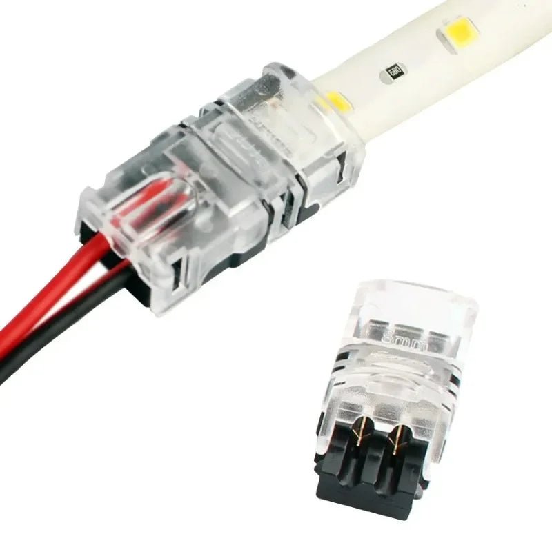
Product Reference
This page shows one connector format. Connection details are checked against the actual LED strip and installation before a quotation is confirmed.
A two-contact connector is often selected for a simple two-wire light circuit, but matching the contact count is not enough. Confirm the strip’s positive and negative marks, the position of its cut pads and the connector’s usable board width. A coating or silicone jacket may also change how the contacts seat.
Read the connector selection guide →Selection Checks
The contact count is only the first filter. These details help prevent an apparently matching connector from failing in the finished installation.
Identify the strip’s printed positive and negative contacts and the lead arrangement. Verify polarity before energizing the connection.
Share a straight-on photograph of the pad area. Check PCB width, pad placement, surface coating and whether the clip closes fully.
The clip is wider and taller than the bare strip. Check enclosure clearance, cable exit and access for future service.
Installation Fit
Strip to wire or strip to strip? The pictured AL0201 pairs a two-contact clip with a two-wire lead for a strip-to-wire connection. Joining two strip sections directly requires a different joint arrangement; specify that requirement rather than selecting by two pins alone. Compare the roles in the solderless LED strip connectors guide.
A clip can simplify assembly when the selected strip presents the right pads and the surrounding space allows the connector body. It does not automatically suit every COB or SMD strip, nor does the clip alone establish an environmental rating. If the strip is installed inside a silicone profile, send the section or available cavity dimensions as well.
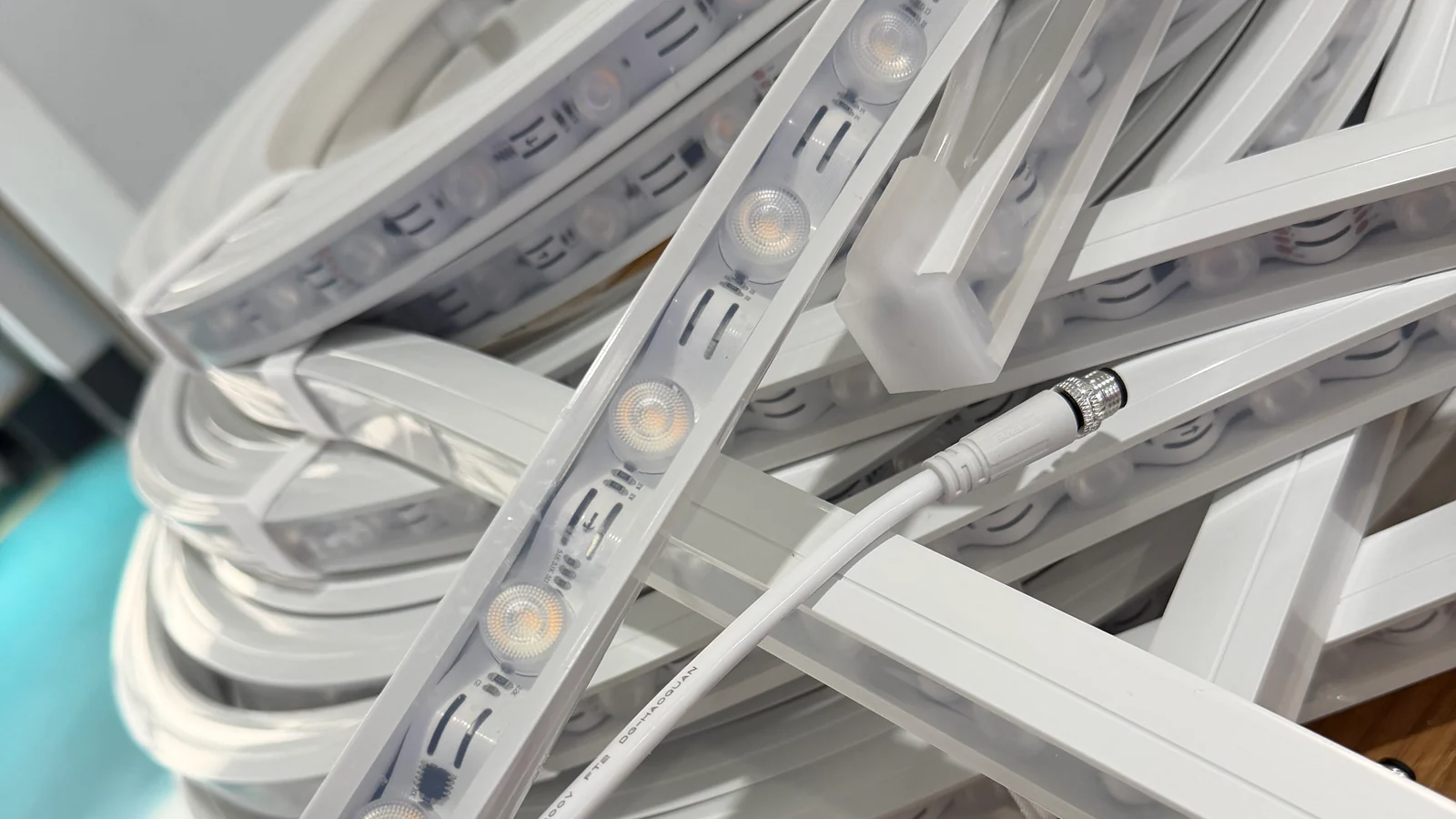
Provide the strip model or a clear cut-end photograph, available space, connection route and expected quantity. If you are replacing an existing connector, photograph both mating ends and the controller markings.
We can review the appropriate lead or clip format from those details rather than assuming that contact count alone confirms compatibility.
Compare the 4-pin AL0401 lead format →Common Questions
No. Contact count, PCB width, pad position, coating and the connector body clearance must match the selected strip.
The shown clip-style format makes contact without a soldered joint when it is matched and seated correctly. The selected assembly still needs inspection.
Only after checking the tube’s internal clearance, the connector body and cable exit. Send the selected tube section for review.
Provide the strip reference or a clear cut-end photo, PCB width, polarity marks, installation space, cable route and quantity.
Request a Quote
Send the strip contact photo, board width, cable route and quantity. We will review the matching interface before confirming the connector format.
PROJECT ENQUIRY
Leave your contact details and a short project note. We will follow up with you.