
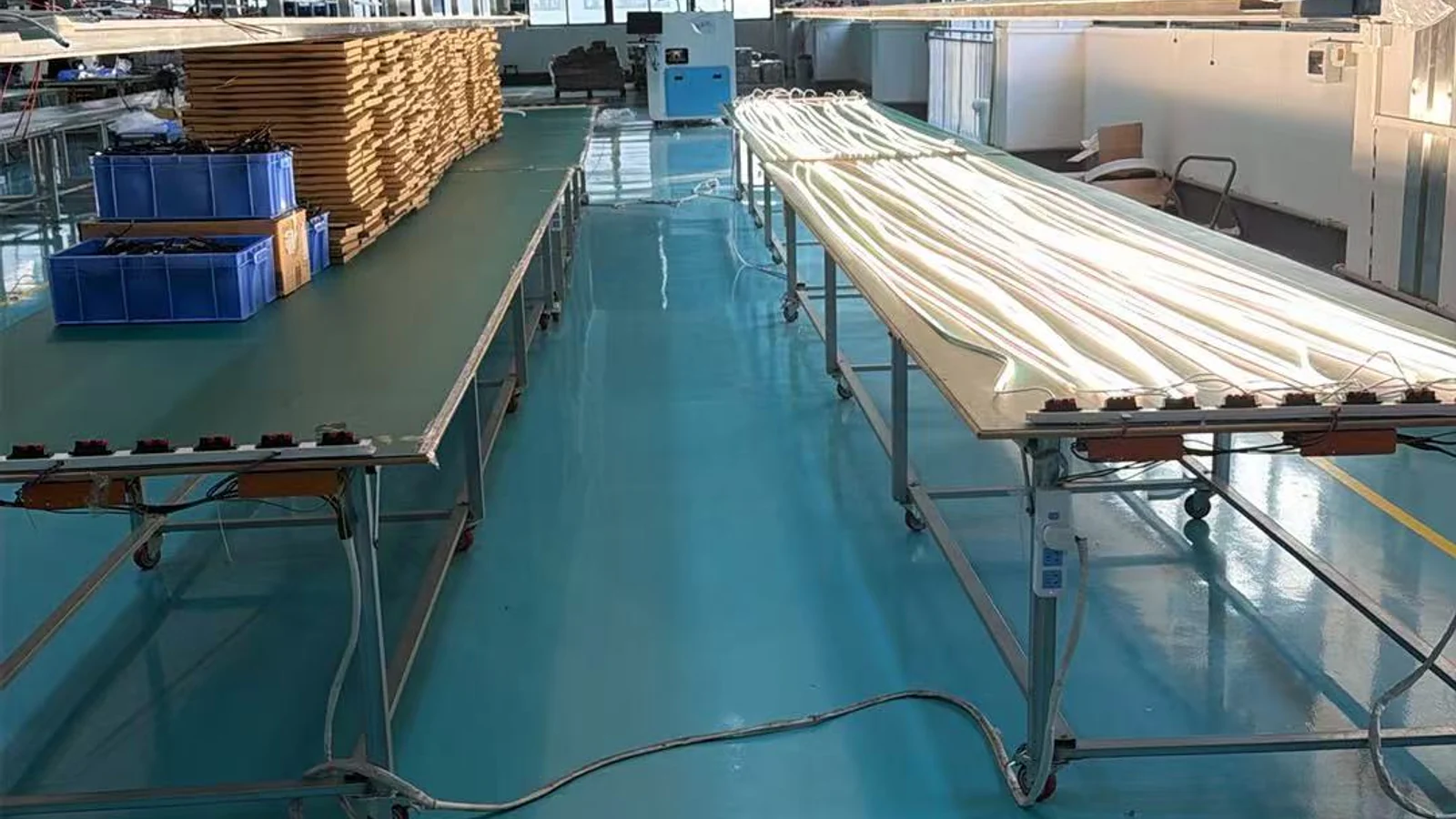
LED strip heat dissipation is an assembly question. Heat moves from the LED strip through its contact layer and mounting surface, then into the surrounding structure and air. Strip power, contact quality, profile material, enclosure volume, ambient conditions and operating pattern all influence the result, so a single rule cannot replace review of the selected components.
AlisterTech can help define the silicone housing and its fit around the strip and mounting structure you have selected. Bring the profile section into the same enquiry as the proposed contact layer and enclosure space. Where the surrounding structure forces another shape, custom extrusion can be discussed. The thermal requirement should stay attached to the actual strip and installation, rather than becoming a generic claim about the housing material.
Short answer: Use the exact strip data, mount it against a suitable continuous surface, avoid gaps that interrupt contact, provide space for heat to leave the enclosure, and test the complete assembly under representative operating conditions.
1. Treat Heat Dissipation as a Complete-System Decision
The strip, adhesive or bonding layer, mounting surface, enclosure and surrounding construction form one heat path. A change in any part can change the operating condition. For example, the same strip can behave differently on an exposed metal channel, inside a closed cabinet or within a flexible silicone assembly.
Begin by drawing the physical stack from the strip to the surrounding environment. Show which surfaces touch, which spaces are enclosed and where air can move. This prevents the profile name or strip appearance from being used as a substitute for the actual installation.
2. Start With the Exact LED Strip Data
Use the electrical and operating information for the selected strip model. Package type or LED density alone does not define the heat load. Confirm the intended length, supply arrangement, control method and normal operating pattern. If dimming or intermittent use is planned, include that information without assuming it removes the need for thermal review.
Check whether connection points, soldered areas or control components create local space or contact differences. The LED Strip Lights page is the correct starting point for product selection, while the LED strip testing guide explains how to verify the selected assembly before installation.
3. Create Continuous Contact With the Mounting Surface
A mounting surface can only receive heat effectively where contact exists. Clean the surface as required for the selected bonding method and avoid dust, oil, uneven joints or raised fasteners that create gaps. Keep the strip straight and supported rather than bridging over recesses.

Adhesive attachment is part of the mechanical and thermal path, but it should not be treated as a universal solution. Surface material, finish, temperature and maintenance needs affect the attachment method. Follow the selected strip and mounting-system instructions.
4. Review Profiles, Silicone Tubes and Enclosures by Function
A metal profile may provide a heat-spreading surface when the strip is installed with suitable contact, but its effectiveness still depends on profile size, surrounding construction and airflow. A silicone tube or diffuser primarily serves optical, protective or geometric functions and should not automatically be described as a heat sink.
When a strip is installed inside a tube or profile, check the usable internal space, strip position and contact surfaces. Do not compress components or force the strip into a channel. Use the strip-to-profile matching guide to review fit, and the LED Silicone Tubes page for the available product route.
5. Include the Enclosure and Ambient Conditions
Document whether the assembly is exposed, recessed, enclosed behind glass, inside furniture or close to another heat source. Note the surrounding materials and whether air can circulate. Direct sun, sealed cavities and nearby equipment can change the environment even when the strip itself is unchanged.
Review the worst representative operating condition, not only a short bench test in a cool room. If the installation is enclosed, test the enclosure in its normal orientation with its intended covers, diffusers and controls fitted.
Read the Silicone Temperature Range Against the Named Material
A silicone rubber temperature range belongs to the named compound and the conditions stated in its documentation. The material description alone does not establish a working-temperature limit for a powered LED assembly. If heat resistance matters to your purchase, request the applicable material file together with the exact lighting configuration.
- Material: identify the supplier, compound or grade, document revision, exposure duration and test conditions. Distinguish any stated continuous-use information from short-duration exposure or a processing condition.
- LED and other components: use the selected source, connector, cable and related component documents. An LED junction limit, a specified measurement-point limit and ambient temperature describe different things; do not substitute one for another.
- Installed assembly: record the mounting surface, enclosure, nearby heat sources, operating pattern and measurement method. A material rating does not demonstrate that this complete construction meets its operating requirements.
Cree LED’s thermal-management guidance distinguishes the LED junction, thermal path and ambient conditions. Its component examples are not specifications for an AlisterTech product. Request the applicable material and product documents for your order, then agree the sample-review conditions with the quotation. A numerical limit needs evidence for the selected material and configuration.
Buying for Heat Exposure? Define the Acceptance Conditions
A request for a “heat-resistant silicone profile” should identify what will be exposed, where the temperature will be measured and how long the exposure lasts. Send the housing section, exact LED source and mounting detail together. A material property cannot stand in for acceptance of the powered lighting assembly.
If a project specification refers to a silicone melting point, ask which material document and evaluation method it requires. Do not turn an internet material value into an operating-temperature claim on the purchase order. List the material evidence and assembled-sample checks separately so the supplier can identify what is supported for the quoted construction.
For AlisterTech’s review, attach the relevant specification page, intended exposure and a dimensioned section to your profile quotation request. Ask the quotation to distinguish the silicone housing, light source and other components included in supply, and to name any documentation still needed before approval.
6. Test the Complete Assembly Before Repetition
Build a representative sample using the selected strip, mounting surface, profile or tube, diffuser, power arrangement and enclosure. Operate it under the intended control condition for a suitable evaluation period, following the component instructions and applicable electrical practices.
Record the sample configuration so a change in strip, surface or enclosure is not mistaken for the same test. Visual appearance alone does not confirm an acceptable thermal condition. Where temperature limits are specified by the selected components, use an appropriate measurement method and compare the result with that documentation.
Include cable entries, connectors and soldered sections in the review. A local connection can sit differently from the rest of the strip and may be surrounded by extra insulation or reduced contact area. Check these details in their installed position instead of assuming that a measurement taken only at the centre of a straight run represents every part of the assembly.
Repeat the check if the strip model, mounting layer, profile, cover or enclosure changes, because the earlier result no longer represents the same construction.
7. Information to Share for Assembly Review
- Selected LED strip model and data
- Installed lengths and operating pattern
- Supply and control arrangement
- Mounting surface material and shape
- Profile, tube or diffuser section
- Bonding or fixing method
- Enclosure size and cover details
- Nearby heat sources and exposure
- Connection and cable locations
- Representative sample requirement
Common Heat-Dissipation Mistakes
Using Package Type as a Thermal Specification
The finished strip and drive arrangement determine the operating load. Use exact model data.
Mounting Across Gaps or Uneven Surfaces
Interrupted contact can prevent the support surface from working as intended. Prepare a continuous mounting path.
Testing the Bare Strip Only
A bare strip in open air does not represent a strip inside a profile, tube, cabinet or sealed detail.
Assuming Every Profile Solves Heat
The material, section, contact and surrounding construction must be reviewed together. A product name is not a thermal calculation.
Frequently Asked Questions
Does every LED strip need a metal profile?
Not every installation is identical. The need and profile choice depend on the selected strip, surface, enclosure and operating conditions. Follow the strip documentation and test the complete assembly.
Can silicone dissipate LED strip heat?
Silicone may be part of the optical or protective assembly, but it should not be assumed to provide the same heat-spreading function as a suitable metal surface. Review the actual construction.
Is touching the strip enough to judge temperature?
No. Touch is subjective and does not establish component temperature. Use a defined measurement method when limits need verification.
Can dimming reduce thermal load?
Operating conditions can affect load, but the actual control pattern and component data must be considered. Do not use a general assumption instead of testing the planned configuration.
What should be tested before a repeated installation?
Test a representative section with the real strip, mounting surface, profile or diffuser, connections, enclosure and intended operating pattern.