
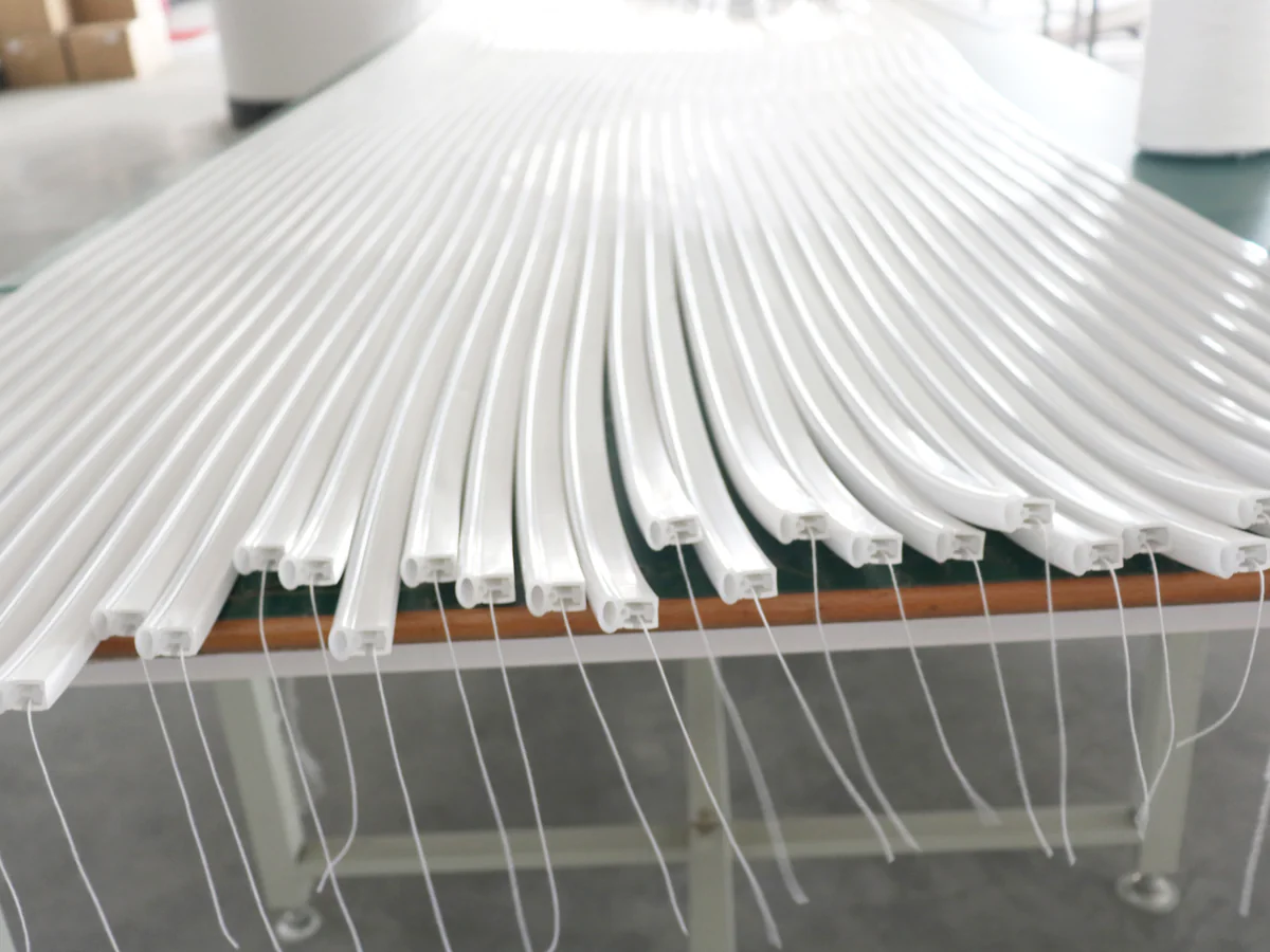
Custom silicone extrusion tolerances should start with the fit your product needs, not an assumed factory-wide accuracy figure. Identify the dimensions that control the LED strip, mounting interface and end connection; then agree the allowable variation and inspection conditions before releasing tooling. A nominal dimension, a requested tolerance and an accepted production requirement are different things.
For OEM lighting buyers, a useful drawing explains what must fit, how it will be checked and which requirements are still open. This guide covers that dimensional discussion. The tooling guide covers tooling scope, while the sample approval checklist covers the wider assembled product.
Why Dimensional Requirements Matter in Custom Silicone Profiles
A profile can match the intended outside shape yet fail at the interface that matters. An internal passage may restrict insertion of the selected LED board. A retaining feature may not suit the surrounding channel. An end cap may fit the outside section but leave insufficient cable space.
Begin with four separate records:
| Record | What it establishes | What it does not establish |
|---|---|---|
| Target dimensions | The intended geometry and units | A confirmed manufacturing tolerance |
| Agreed dimensional limits | The variation accepted for identified features | Approval of every other product characteristic |
| Sample acceptance conditions | How a stated sample revision will be checked | Automatic release of future production |
| Production control requirements | The agreed inspection basis for the order | A universal capability applying to every profile |
Keep these records linked to the same drawing revision. A photograph or an attractive rendering cannot establish a dimensional acceptance limit. AlisterTech's custom extrusion review starts from your drawing, sample or installation requirement; project-specific limits still need agreement.
Which Dimensions Should Be Defined First?
Overall width and height
Show the outside envelope and installed orientation. Distinguish a nominal profile width from the maximum space available in the recess. If adjacent surfaces limit the height, include that surrounding detail rather than asking the supplier to infer it from the product sketch.
Internal channel clearance and LED strip fit
Identify the board width, component height and insertion route. Include solder joints, protective coatings or connectors where they affect clearance. An empty channel that accommodates a bare PCB does not necessarily accommodate the complete strip. Mark whether dimensions refer to the unloaded section or the assembled condition.
Wall thickness
Identify the walls that matter to clearance, support or the visible face. Do not assume every wall has the same function or must have the same limit. Where appearance matters, retain a separate light-appearance review with the intended strip; a wall measurement alone does not approve the illuminated result.
Mounting interfaces
Mark the surfaces that locate, retain or support the profile. Supply the mating channel, bracket or groove drawing when available. Explain whether the installation uses insertion, sliding or another arrangement. Avoid approving retention from an isolated section drawing without considering the actual support.
Cable exits and critical assembly dimensions
Show the cable route, termination space and end treatment. A continuous extruded cross-section does not by itself define the finished end connection. Label the interfaces that cannot change and explain the consequence of interference, loose fit or insufficient access.
How to Mark Critical Dimensions on a Profile Drawing
Use stable reference surfaces and label the few measurements that control function. A drawing note such as "critical: LED board clearance" is more useful when accompanied by the actual board reference and the condition in which clearance is assessed.
- Identify the drawing number, revision and units.
- Mark each critical feature with a consistent identifier.
- State its functional purpose and mating part.
- Separate nominal values from requested limits.
- Flag unresolved requirements for discussion before tooling release.
- Record the agreed measurement condition and acceptance method.
Do not make an ambiguous sketch look final by adding arbitrary decimal places. If your installation needs a particularly restrictive limit, explain why and ask for feasibility review. Do not transfer a tolerance from a different profile, material or manufacturing process.
For example, a drawing register can describe an internal opening as "strip clearance; target supplied; acceptable limits to be agreed." That is a request for review, not a released production specification. Once agreed, update the controlled drawing instead of leaving the decision only in an email.
Factors That Can Affect Extruded Profile Dimensions
An extrusion die and the finished flexible profile are not interchangeable measurement references. WACKER's material-processing guidance describes die swell, cross-sectional flow and the influence of take-off stretching on extruded silicone geometry. These are general processing considerations, not evidence of AlisterTech's numerical accuracy or material sourcing. See WACKER's processing guide, extrusion section.
For a purchasing review, connect the proposed section, material requirement and processing discussion to the finished condition you intend to inspect. Narrow passages, wall transitions and locating features should be considered together rather than independently tightened without an assembly reason.
Measurement can also change the apparent result. A flexible wall may deform under contact pressure; a section supported differently during inspection may not represent the same condition. Agree how the sample is supported and avoid stretching it while assessing the cross-section. Discuss suitable measurement equipment with the supplier rather than treating a compressed reading as the free-state dimension.
Cross-sectional fit and finished cut length are different requirements. Specify each where it matters. This guide does not assign a tolerance class or a numerical capability to your project. If your drawing invokes a technical standard, its scope, edition and intended application need separate review before acceptance.
How Tooling and Sampling Support Dimensional Review
Before tooling, identify which features are approved and which remain targets. Agree whether the proposed section needs changes to suit the strip, support or end assembly. A tooling quotation should not be interpreted as acceptance of an unstated dimensional requirement.
Use the trial profile to compare the processed section with the agreed basis. Feedback should identify the feature, drawing revision, measurement condition and observed issue. "Too tight at the selected board's solder joint" provides a clearer next step than "make it bigger."
Where a revision is proposed, review its consequences for the other interfaces. Enlarging a channel without considering the outside envelope, wall or mounting feature can move a problem elsewhere. Recheck the changed sample against the updated requirements before deciding whether to release it.
The manufacturing page shows actual processing and assembly context. Those images and videos explain the work being discussed; they do not prove that a particular sample has met an unrecorded tolerance.
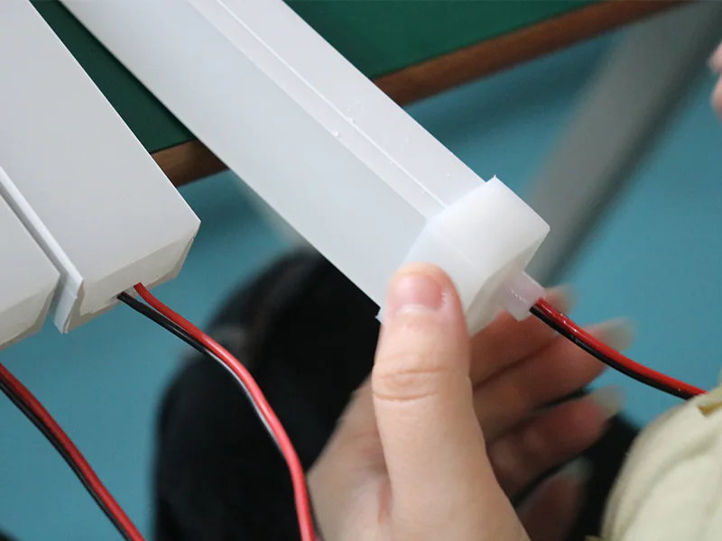
How to Inspect a Silicone Profile Sample
Agree the inspection basis before the sample arrives. Record its reference, drawing revision, material identification where supplied, and whether you are checking an empty housing or a finished lighting assembly. Confirm the condition and timing of measurement with the supplier; do not substitute an assumed universal waiting period.
Use a feature register to keep observations actionable:
| Feature | Inspection question | Record to keep |
|---|---|---|
| Outside envelope | Does the section fit the defined installation space? | Drawing revision, support condition and result |
| Internal opening | Does the selected strip fit by the agreed method? | Strip reference, local interference and fit observations |
| Wall or locating feature | Was the feature assessed without unintended deformation? | Measurement method and agreed limits |
| Mounting interface | Does the actual mating component locate and retain the section? | Mating-part revision and assembly observations |
| End connection | Are cable routing and end clearance suitable? | End detail, cable reference and unresolved points |
Keep measured values separate from acceptance decisions. A value without a defined limit cannot establish pass or fail. Conversely, a successful assembly check may address fit but does not replace every required dimensional measurement.
Record open items explicitly. A sample can be acceptable for one feature while another remains unresolved. The quality-control page explains the product-specific review scope; the inspection record for your order should state which checks actually apply.
What to Send Before Requesting a Custom Extrusion Quote
Send the current section drawing or sketch, mating-interface detail and selected strip information. Identify critical dimensions, requested limits and any dimensions that are only preliminary targets. Add the installation environment, end connection, required lengths and estimated quantity.
If you have a physical sample but no controlled drawing, explain what must remain equivalent and what may change. A sample can support discussion, but worn, compressed or modified features should not silently become the production reference.
For AlisterTech custom silicone profiles, the stated starting MOQ is 200 m; final applicability depends on the profile and quoted scope. Do not treat that commercial starting point as a tolerance commitment. Use the extrusion quote guide to prepare the broader request without duplicating the dimensional register.
Before confirming the order, ask that the quotation, drawing and sample decision reference the same revision. Keep the agreed limits and inspection requirements accessible to the people receiving the production parts, not only the designer who reviewed the first sample.
Frequently Asked Questions
How are tolerances agreed for an AlisterTech custom silicone profile?
Tolerances are agreed for the specific section, material requirements, critical features and inspection conditions. Mark the dimensions that control fit and send the drawing or sample for review before tooling. The custom extrusion enquiry should identify requested limits rather than assume a universal numerical tolerance.
Is a target dimension the same as an accepted tolerance?
No. A target describes the intended value. Accepted limits describe the variation agreed for a defined feature under stated inspection conditions. Keep preliminary requests separate from released requirements.
Should every profile dimension have the tightest possible limit?
Identify the features that control function first. Explain their assembly purpose and discuss appropriate limits; do not assume the same restrictive requirement is necessary or feasible for every feature.
Can an LED strip fit check replace dimensional inspection?
A fit check can assess the selected strip and insertion method. It does not automatically verify every drawing dimension, mounting interface or end connection required by the order.
Does approval of a first sample automatically approve production?
No. Record what was reviewed, any open items and the accepted revision. Production release should reference the agreed drawing, sample basis and order-specific inspection requirements.
What if I only have a sketch or physical sample?
Send it with the installation detail, strip specifications and features that cannot change. Mark unknown requirements clearly so the dimensional and quotation review can identify what needs definition before tooling.
Review the Dimensions That Matter
Send your drawing, section sketch or sample requirement. Mark the critical interfaces and include the LED strip, installation detail and estimated quantity.