
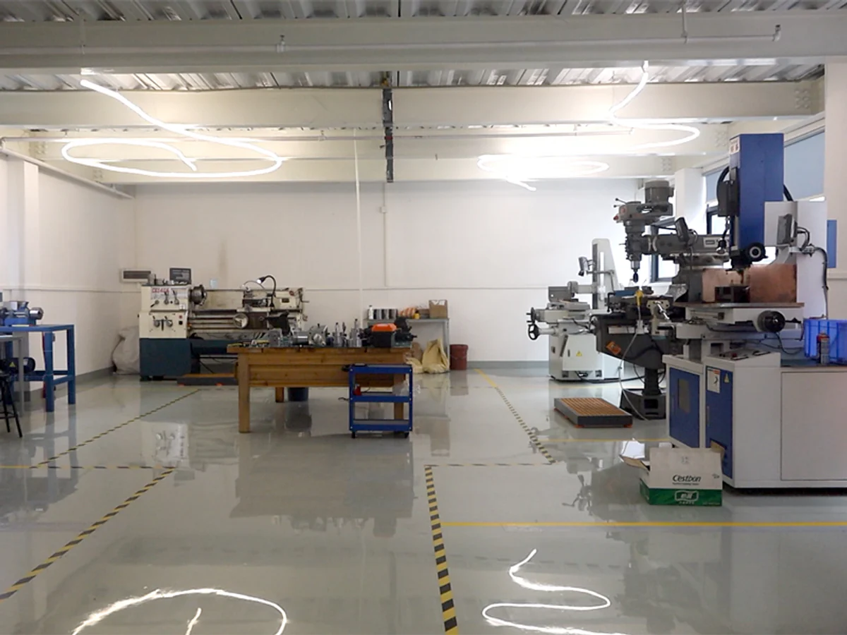
Silicone extrusion tooling converts an approved cross-section into the die and process setup used to form a continuous profile. You do not need to design the tool itself, but you should confirm the geometry, material target, functional interfaces and sample criteria before tooling begins.
Short answer: Freeze the profile revision, identify critical dimensions and interfaces, confirm the material and supply format, then use the first sample to compare the processed profile with the approved basis. Tooling is part of development, not a substitute for clear design inputs.
1. What Extrusion Tooling Controls
The die establishes the continuous cross-sectional form that leaves the extrusion process. It is developed around the approved section, including outside geometry, internal openings and the relationships between walls, channels and locating features. The resulting physical profile is also influenced by material and processing, so a rigid drawing should not be treated as the finished sample.
Tooling does not define the project by itself. It cannot decide where the LED strip sits, which face emits light or how a cable should leave the product. Those decisions belong in the approved profile requirements before tooling begins.
2. Confirm the Profile Before Tooling
Use one controlled profile drawing. It should show units, section orientation, key dimensions and the revision approved for tooling. Attach the LED strip, installation and connection information that explains why the geometry matters. If a physical sample is the source, record which features will be reproduced and which will change.
Classify dimensions by function. A dimension that locates the profile in an existing groove is different from a reference dimension used only to describe the shape. This helps the engineering review focus on fit-critical relationships rather than assigning the same priority to every line.
3. Review Geometry as a Complete Cross-Section
Simple and complex profiles should both be reviewed for how the section behaves as one shape. Thin walls, internal channels, narrow openings, sharp transitions and large differences between neighboring sections can affect how the material forms and holds its geometry. The correct response is not to invent a universal design rule, but to review the actual section before tooling begins.
Ask whether each feature supports installation, lighting or assembly. Removing unnecessary detail can make the design easier to control without changing the application. When a feature is essential, label the interface it supports so a proposed adjustment can be evaluated against the real function.
4. Confirm Material Targets With the Geometry
The material target should be discussed together with profile geometry. Hardness, visible color and diffusion objective can influence handling and the way the profile behaves, but a hardness value alone does not describe the finished part. Wall relationships, hollow space and installation all matter.
Do not copy a material specification from an unrelated seal or profile. State the project requirement and the evidence available. Product-specific documents, where applicable, should be confirmed for the quoted material and market rather than assumed from a general supplier file.
5. What the Trial Extrusion Is For
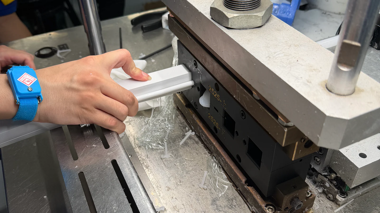
The trial produces a physical sample from the current tooling and material basis. It allows the processed section to be compared with the approved drawing and the intended assembly. This is where a design that was previously viewed on screen can be checked for fit, orientation and visible details.
Keep the trial sample tied to its drawing revision. If several versions are produced, label them clearly. An unlabeled sample can create confusion later when feedback refers to a different geometry or material basis.
6. Review the Sample Against Defined Criteria
Start with the features that affect use: overall fit, strip position, emitting face, mounting interface, cable exit and end details. Then review visible surface and profile consistency. Separate observations from acceptance requirements. A photograph can document a visible issue, but dimensions or agreed functional checks should support decisions about fit.

Test the sample in the intended assembly when practical. A loose profile on a desk does not show the same relationships as the profile installed with the selected LED strip and adjacent parts. Use the silicone profile sample approval checklist to structure the review.
7. When a Tooling Revision May Be Needed
A revision may be considered when the actual section does not support the approved fit, when the design basis changes or when sample feedback identifies a necessary geometry adjustment. The reason should be recorded before work proceeds. This distinguishes correction of the current basis from a new customer-requested design.
Do not communicate changes as vague comments such as “make it tighter” or “more flexible.” Mark the affected feature, explain the installed result and update the drawing where geometry changes. Keep one current revision so the next sample can be compared with a clear target.
8. What Affects Tooling and Sampling Scope
Commercial scope can change with cross-section complexity, internal features, material or color requirements, sample quantity, secondary assembly and the number of review cycles. These are project factors, not a published universal price or lead-time formula. A supplier needs the actual drawing and requirement before confirming them.
You can reduce uncertainty by providing a stable drawing and consolidated feedback. Do not begin tooling while critical installation, strip or connection decisions are still changing. The silicone extrusion process guide explains the broader manufacturing sequence without replacing a project-specific review.
When comparing quotations, check what the tooling and sample lines actually include. One quotation may cover only a die and plain profile sample, while another may include selected material, cut pieces or assembly work. Ask each supplier to identify the drawing revision, sample configuration, review scope and ownership of any open decisions. This creates a like-for-like comparison without assuming that similarly named line items represent the same deliverable.
Also confirm how sample feedback will be recorded. A short decision log linking comments to the drawing revision keeps commercial discussion, geometry changes and approval status aligned.
Tooling Preparation Checklist
- Controlled cross-section drawing
- Fixed, target and reference dimensions
- Installed orientation and interfaces
- LED strip and component envelope
- Light and bending directions
- Material, color and diffusion target
- Cable and end details
- Required sample configuration
- Sample review criteria
- Named drawing revision
Common Tooling Mistakes
Starting Tooling From an Uncontrolled Sketch
A sketch can start development, but the geometry sent for tooling should be identifiable and revision controlled.
Changing the LED Strip After the Channel Is Approved
A different strip or connection area may change internal fit and emitting position. Review the new combination before continuing.
Evaluating Only the Outside Shape
Internal openings, walls and interfaces can control how the part assembles and behaves. Review the full section.
Sending Feedback Without the Installed Context
Show where the issue appears in the assembly and which requirement is not being met. This makes the requested change reviewable.
Frequently Asked Questions
Does every custom profile require dedicated tooling?
A genuinely new continuous cross-section normally requires a tooling basis. Whether an existing format can be used should be checked against the current profile requirement.
Can tooling be made from a physical sample?
A sample can establish the starting geometry, but wear or deformation may have changed it. Confirm the intended section in a controlled drawing before tooling begins.
Does the first sample automatically approve production?
No. The sample should be reviewed against the agreed drawing, assembly and acceptance criteria. Resolve any remaining questions before production starts.
Can tooling cost or timing be confirmed without a drawing?
A reliable project confirmation needs the actual section and scope. Generic figures can mislead when geometry, material or sample requirements differ.
What should you send for review?
Send the drawing or sample, key dimensions, LED strip, installed orientation, material target, connection details, sample requirement and estimated quantity.