Visible Sides
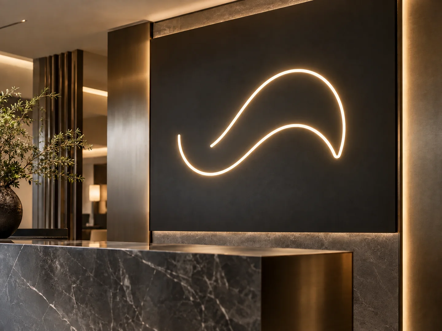
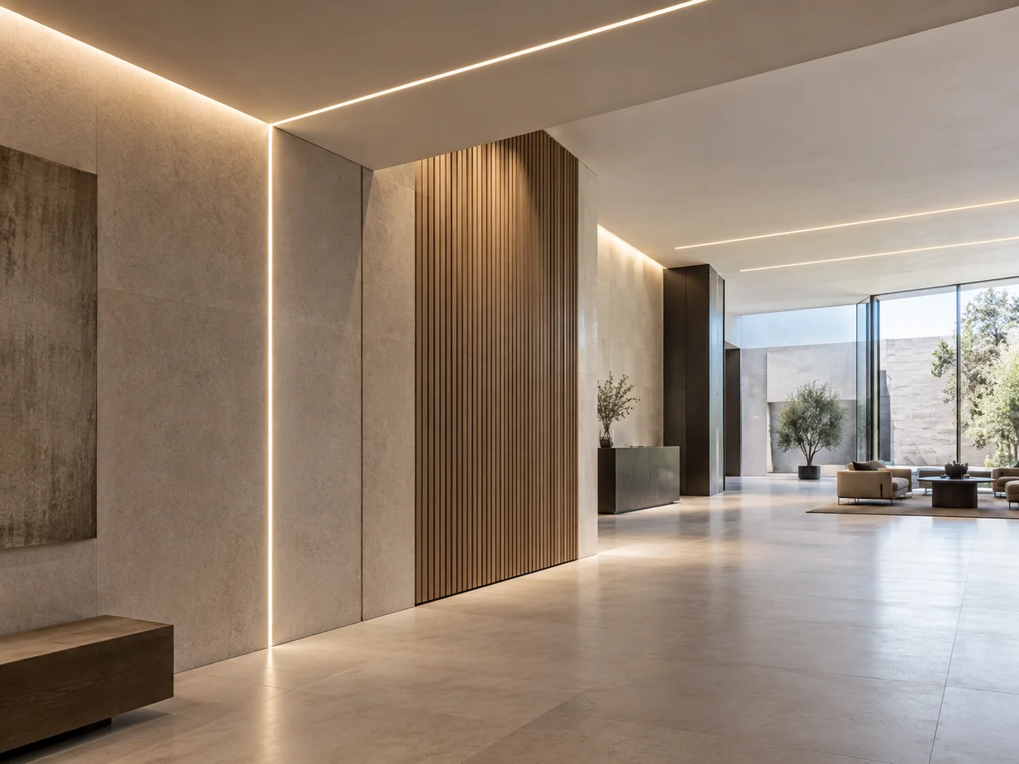
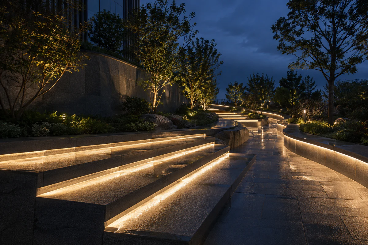
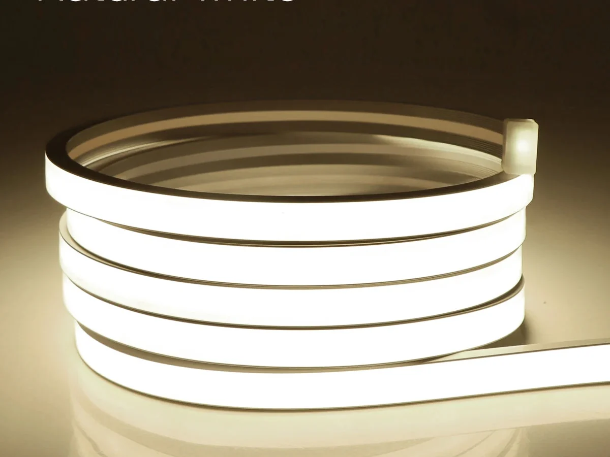
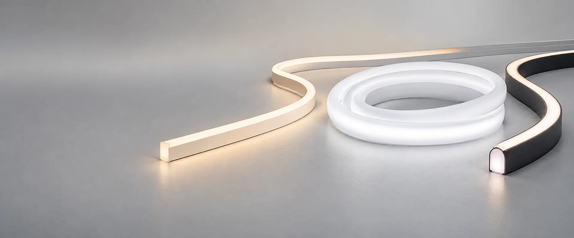
Show whether the light will be viewed from the front, side or below, then confirm the visible light appearance with the selected configuration.

LED Neon Flex Series
AL-HR11-B24WB12066
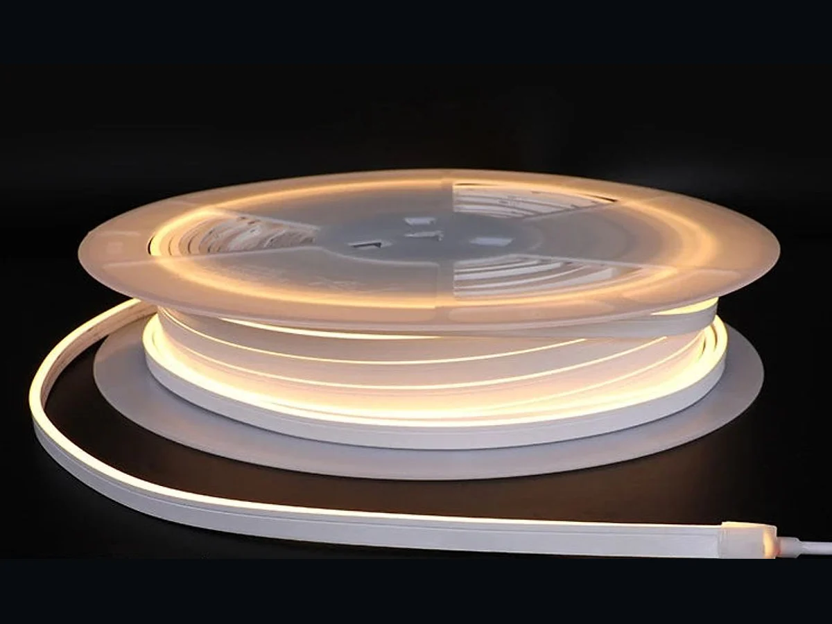
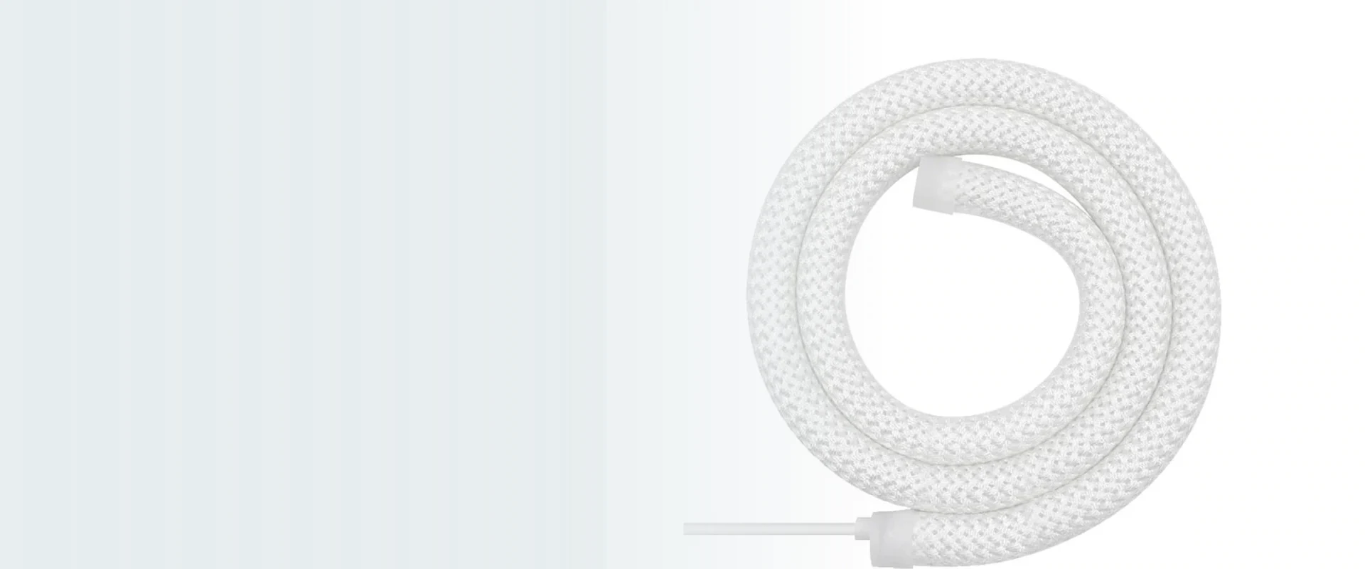
Choose this 16mm round LED neon flex by its V2 catalogue configuration. Compare the round profile, three LED and colour options, and DC 24 V assembly details before confirming your installation.
Catalogue Configurations
These V2 catalogue rows belong to the 16 mm round profile shown on page 15, No.6. Select the LED and colour columns, and include the full AlisterTech configuration code in your enquiry.
| AlisterTech configuration | LED type | LEDs/m | Colour | CRI | Cut length | lm/m | PCB | Voltage | W/m | Finished size (mm) | IP |
|---|---|---|---|---|---|---|---|---|---|---|---|
| AL-HR11-B24WB12066 | SMD2835 | 120 | White / Red / Blue Green / Yellow | >80/90 | 50mm | 1050 | 2*6mm | DC24V | 10*2 | 5000*R16 | IP67 |
| AL-HR11-B24RGB12066 | SMD2216 | 280 | 2700-5500K | >90 | 50mm | 1050 | 2*6mm | DC24V | 10*2 | 5000*R16 | IP67 |
| AL-HR11-B24RGB10266-2811 | SMD3838 | 120 | RGB | / | 50mm | 460 | 2*6mm | DC24V | 12*2 | 5000*R16 | IP67 |
Specifications vary by LED configuration and model. Confirm the final quoted configuration and current technical documentation before ordering. A slash is retained where no CRI value is listed; CRI entries and values containing * are reproduced as printed. Finished-size values are not a maximum single-feed length.
IP67 is listed for these catalogue configurations. Protection performance depends on the complete assembly, including cable exits and end treatment. Confirm the quoted configuration for the intended environment.
Cross-Section & Dimensions
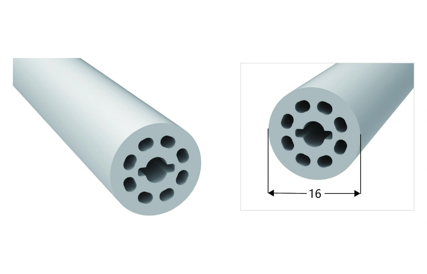
The V2 catalogue shows a 16 mm round section. Review its internal channels, mounting route, end connections and selected LED configuration before installation.
diameter 16 mm
Catalogue page 15, profile 6
Review the internal section and selected LED configuration together.
Light & Bending
Show which sides must be visible and assess the selected configuration in a representative sample. The V2 model rows do not specify a numerical emitting angle; do not treat the round outline alone as an angle guarantee.
The installation route still needs a separate bending review. Show the tightest curve, support points and cable exit so the selected length is not twisted or forced beyond the quoted configuration.
Plan the installation route →What to Send
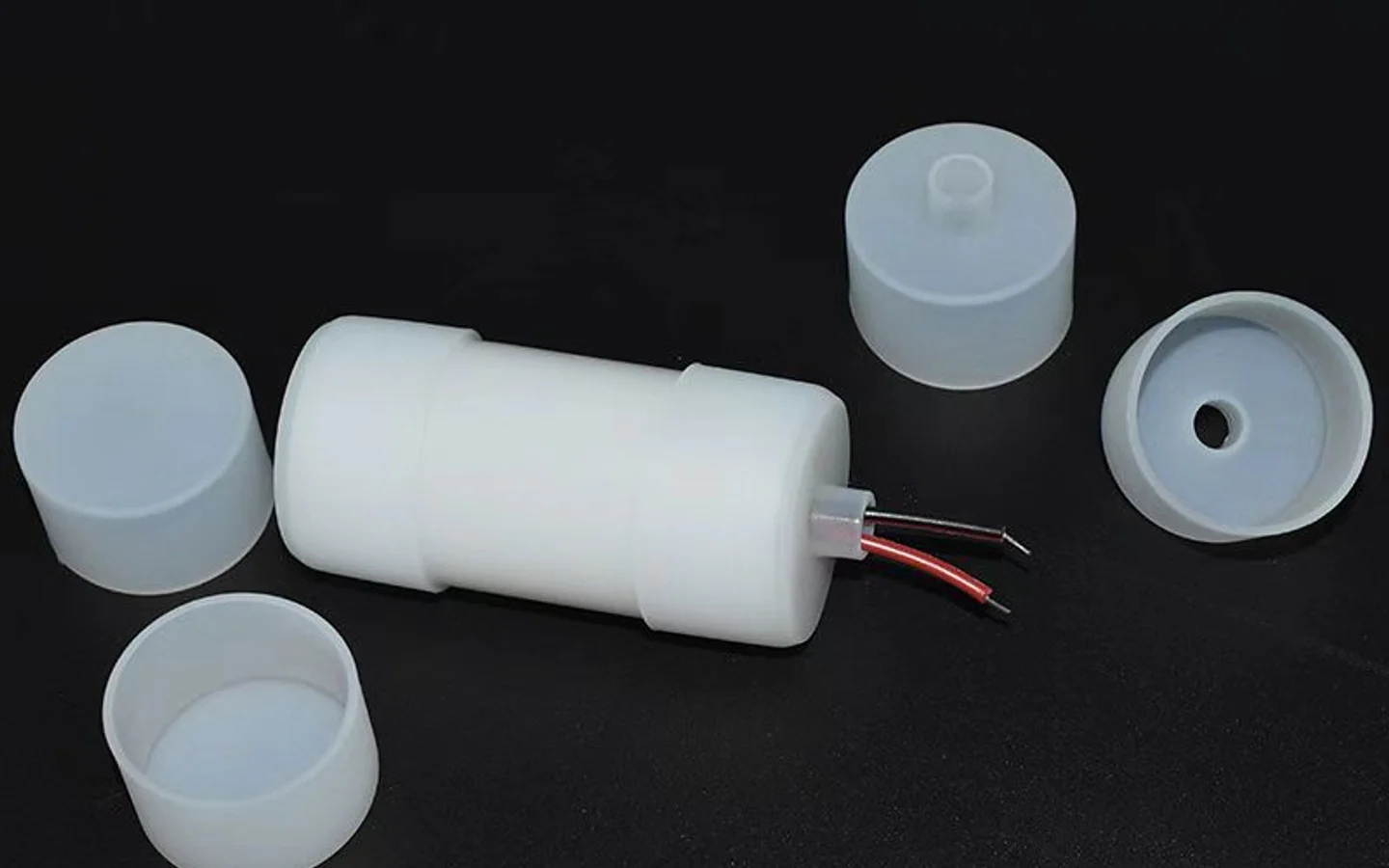
Include the visible sides, curve geometry, fixing method and cable position.
Project Information
The round format should be selected together with the route, support and electrical arrangement.
Show whether the light will be viewed from the front, side or below, then confirm the visible light appearance with the selected configuration.
Provide the path, the tightest curve and the proposed fixing points. Include any transition where the round profile enters a housing or concealed area.
Identify the selected DC voltage, power location, control method and cable route. Include the expected run length and any controller already selected. Package and connection scope are confirmed with the quotation.
Applications
Related Profiles
Request a Quote
Send the route, visible sides, quantity and power or control requirements already available.
Need a different profile geometry? Explore Custom Silicone Extrusion →
PROJECT ENQUIRY
Leave your contact details and a short project note. We will follow up with you.