
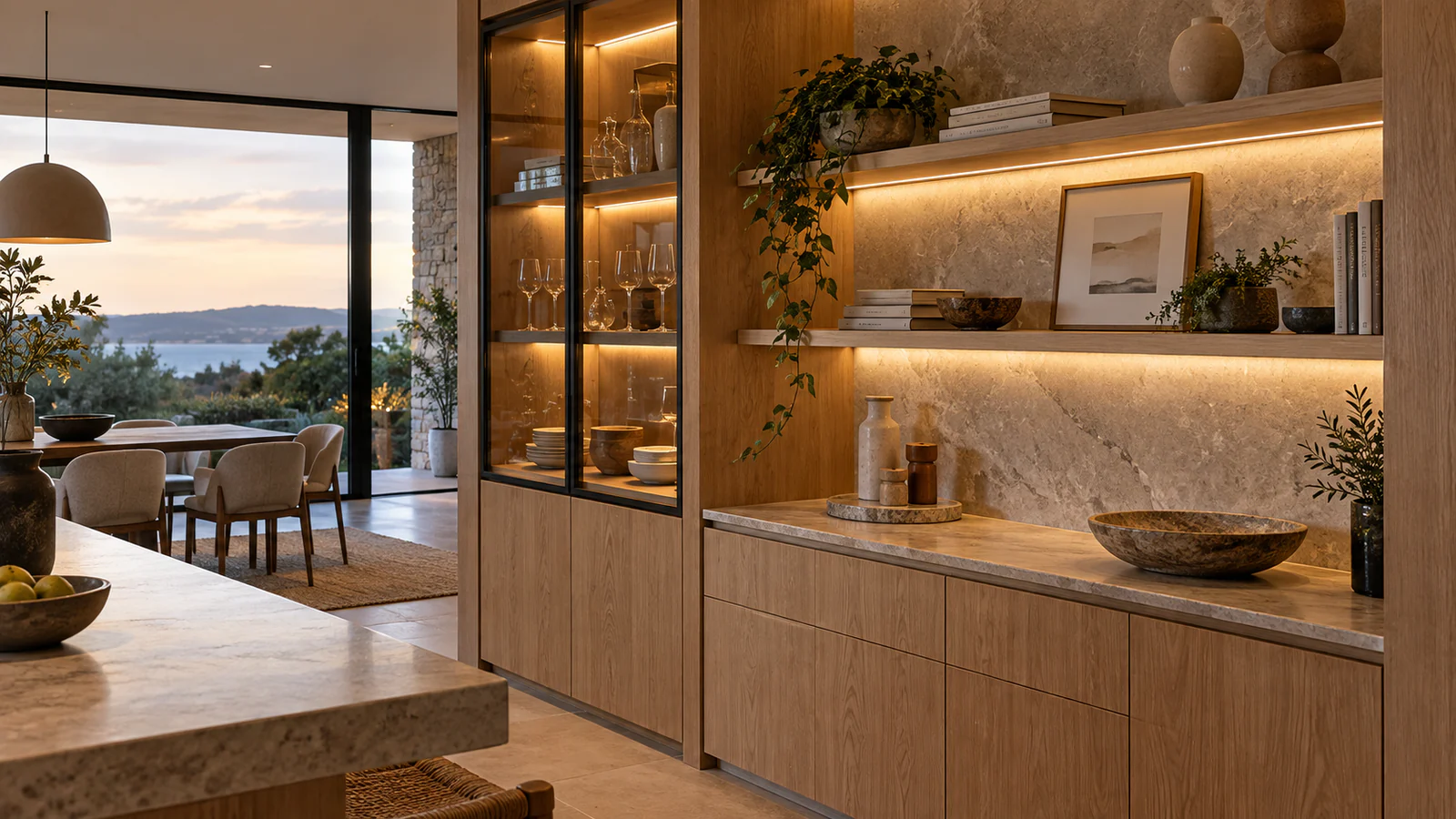
LED cabinet lighting works best when the light source, profile, cabinet section and cable path are planned together. Start with what each compartment needs to do: illuminate a worktop, make an open shelf readable, or add a soft line inside a display cabinet. Then choose the strip and housing around the available space, normal viewing position and access for future service.
Short answer: LED cabinet lighting planning starts with the worktop, shelf or display zone that needs light. For under cabinet LED strip lighting, mark where the light should fall and where the source must stay hidden. Then check the strip, silicone profile or diffuser together with cable exits, power access and maintenance space. Assess the actual cabinet section from the normal viewing position before repeating the detail across a kitchen or a commercial furniture assembly.
Task light or visible accent line?
Keep glare and exposed points in check.
Measure the actual section and components.
Plan cables, control and service.
1. Define the Job of Each Lighting Zone
Under-cabinet worktop lighting and in-cabinet accent lighting solve different problems. A worktop needs useful light where hands and objects are placed. An open shelf may need an even line that does not dominate the objects. A glass-front cabinet may need controlled light that does not reflect directly into the viewer’s eyes. Label these zones separately on the drawing instead of applying one strip position to the entire joinery run.
Record the normal ambient lighting as well as the intended operating scene. A bright strip that looks attractive in a dark sample may be uncomfortable against a reflective worktop. A subtle shelf detail can disappear in a strongly lit room. The desired result should be described from the actual viewing distance and position, not only by a photograph of a bare LED strip.
The Furniture & Cabinet Lighting page introduces the application. This guide concentrates on the physical decisions needed before the cabinet is built.
Under-Cabinet, Shelf and Display-Cabinet Lighting
Kitchen under cabinet LED lighting normally starts with the work surface and the cabinet front edge. LED shelf lighting starts with the objects and their viewing position. A glass display cabinet adds reflections and glare to the review. Concealed linear lighting may hide the source, but concealment alone does not resolve shadows, diffuser appearance or access to the cable.
Compare the COB and SMD light appearance at the intended viewing distance. If the project calls for an assembled light rather than a bare strip, review finished LED neon flex formats. Use profile and mounting documents to identify the selected configuration.
2. Place the Light Around Sightlines and Shadows
Mark the main standing and seated viewpoints. An under-cabinet source placed too far toward the room may become directly visible; placed too far back, it may leave shadows at the front of the worktop. Shelf lighting also changes appearance as objects move. A display shelf and a task surface may therefore need different mounting positions even within the same cabinet elevation.
Use a section drawing to compare the light position with door fronts, shelves, glass, splashbacks and any reflective finish. The edge that hides the LED from one viewpoint might create a shadow from another. Note where the source line begins and ends, particularly at cabinet joints and open corners. This gives the profile and cable exit a defined place rather than leaving them to be improvised during installation.
When a continuous visible line is important, review the complete strip and diffuser together. The LED strip diffusion guide explains why LED spacing, distance to the emitting surface and viewing position all affect smoothness.
3. Choose Between a Strip Assembly and a Finished Flexible Light
A separately supplied LED strip gives a starting point when the cabinet maker controls the housing, diffuser and electrical arrangement. The exact COB or SMD model still needs to be chosen for the intended appearance, dimensions and control method. A silicone tube is a housing for a separately selected strip; it is not a light source by itself.
Finished LED neon flex includes an LED source and may be considered for an exposed line or shaped detail, but its bend plane, section, ends and cable arrangement must suit the cabinet. It should not be used merely because it looks smooth in an isolated photograph. Decide whether the cabinet needs a concealed strip assembly, a visible diffused strip or a finished flexible light before comparing product images.
Do not assume a tube, strip and end cap from different ranges fit together. The selected components should be checked as one physical assembly. Where the cabinet groove or visible finish is unusual, a custom silicone profile may be reviewed against a drawing or sample rather than forcing a standard shape.
4. Measure the Real Space for the Strip and Profile
The cabinet drawing should show the available width and depth after finishes, shelves and hardware are installed. The useful internal channel is smaller than the outside profile dimensions. Check the strip board width, component height, connection body and cable exit within that space. A strip can fit along a straight sample but fail at a joint or in a tight recess when the connector is added.
Identify the emitting face and its orientation after mounting. An edge-facing detail may need a different section from a shelf-facing line. The diffuser must be judged with the actual strip behind it; the unlit profile photograph cannot prove the final illuminated appearance. The strip-to-profile matching guide provides a deeper fit checklist.
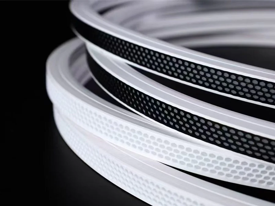
Do not cut a permanent recess based only on a nominal profile size. Review a section sample against the finished cabinet material, especially where a visible edge, door clearance or shelf adjustment limits the installation space.
5. Draw the Cable and Control Route Before Assembly
Show where power enters the cabinetry, how each lit section connects and where the driver or controller can be accessed. Plan cable holes and passages before the cabinet panels are finished. A cable crossing an adjustable shelf path, hinge zone or drawer runner can become visible or vulnerable after the cabinet is used.

The power and control arrangement should come from the exact selected light and its operating data. Do not copy a wiring diagram from a visually similar strip. If the cabinet has multiple zones, label how each zone is controlled and where the connections can be inspected. Where a run crosses between cabinet units, record the joint detail rather than assuming that the light can continue uninterrupted through the construction.
Include the chosen switching location in the review. A physical switch, sensor or external control system can change the cable and component space required. A clean front elevation is only useful when the equipment behind it has a workable route.
6. Keep the Light Detail Maintainable
Plan how a strip, diffuser or flexible assembly can be inspected and removed without damaging surrounding finishes. This does not mean every connection must be visible. It means a defined access path exists and the relevant section can be identified. Removable trim, a service cavity or access from the back of a cabinet may be considered where the furniture construction allows it.
Consider how objects, shelves and doors will change during use. An adjustable shelf can expose a cable or block access. A drawer front may conceal the light when closed but reveal its end when open. Review the detail in normal use, not only in a static presentation image.
Keep the final product reference and section identification with the cabinet drawing. If a replacement is needed later, the exact strip and profile combination should be identifiable without dismantling a working section to discover what was installed.
7. Approve One Representative Cabinet Section
Build or mock up the most demanding section: one that includes a visible light line, a joint, a reflective surface or a tight cable exit. Put the intended strip inside the selected profile and view it from the normal positions under the expected room lighting. Check shadows on the work surface, reflections in glass and the apparent smoothness of the line.
Inspect both the unlit and lit detail. The unlit view reveals edge finish, mounting and cable visibility. The lit view reveals hot spots, glare and uneven transitions. Photograph the approved section with the actual control setting and note any change needed before the same detail is repeated across the cabinet run.
A loose illuminated coil on a table is not a substitute for a cabinet-section sample. The surrounding materials and position are part of the result.
8. What to Send for a Cabinet-Lighting Review
- Cabinet elevation and at least one relevant section
- Task, shelf and accent-lighting zones
- Normal standing and seated viewing positions
- Available width and depth after finishes
- Preferred light appearance and control method
- Existing strip reference, if already selected
- Glass, stone or other reflective surfaces
- Cable route, power location and service access
- Sample bay and estimated total quantity
A dimensioned sketch or a clear photograph can be enough to start. Mark which dimensions and components are confirmed and which are still open for review.
Common Cabinet-Lighting Mistakes
Choosing the Strip Before the Cabinet Section
The strip may fit a shelf width but not its channel, diffuser, connector or cable path. Review the section first.
Ignoring the Normal Viewing Position
A light line that looks smooth from a standing view may expose points or glare from a seated angle. Test both.
Hiding Every Connection Permanently
A concealed connection still needs an access plan. Preserve a route for inspection or replacement.
Approving Only a Rendered Scene
A visual concept communicates intent, not the fit or output of the selected assembly. Approve a representative physical section.
Frequently Asked Questions
Is COB always the best strip for cabinets?
No. COB and SMD should be compared with the intended profile, diffuser, viewing distance and electrical arrangement. The installed sample decides the appearance.
Does a silicone tube include the LED strip?
No. A silicone tube is a housing unless the quoted product is explicitly a finished illuminated assembly. Confirm the scope of supply.
How can visible dots be reduced?
Coordinate strip spacing, profile depth, diffuser construction and sightline. Test the exact strip and profile together.
Where should power equipment go?
Choose a suitable accessible location for the selected equipment and show the cable route on the cabinet drawing. Follow the exact product requirements.
What is the most useful first sample?
A full-size cabinet section with the intended light, profile, viewing angle, surface finish and connection detail is more informative than a bare strip sample.
Coordinate the cabinet detail with the architectural linear-lighting layout, the cove section and display-case sightlines. Where a standard profile cannot fit the joinery, discuss custom silicone extrusion and the sample-to-production process before machining the final groove.