
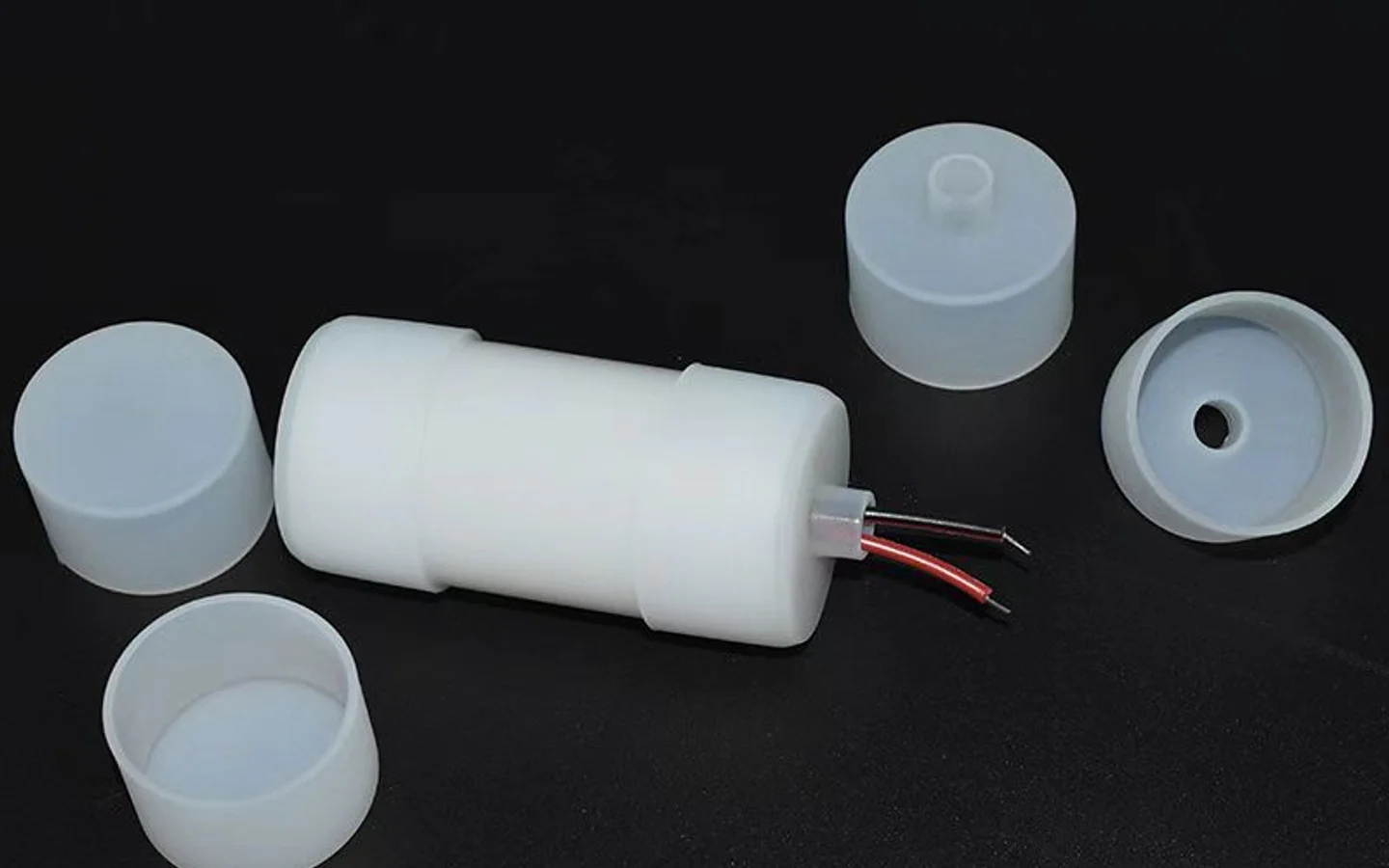
LED neon flex connectors should be selected for the exact finished light, not for a similar-looking silicone outline. The end opening, conductor arrangement, cable exit, electrical control, mounting route and installation environment all affect the connection. Before ordering loose parts or fixing a route, identify the product model and review an assembled end sample.
When the light is supplied through AlisterTech, ask for the end arrangement to be identified with the selected configuration. The accessory information and assembly photographs are useful starting points for discussing caps, cable exits and connection space. A close photograph of an existing end is particularly helpful for a replacement request; it lets the enquiry focus on the actual interface.
Short answer: Match the connector and end cap to the selected neon flex model, then check where the cable leaves the route, how the connection is protected and whether the finished assembly remains serviceable. Do not assume that a connector from another light, or a silicone tube without an LED source, uses the same end treatment.
Identify the finished lighting model.
Compare the section and opening.
Plan entry, exit and access.
Review the complete installed end.
1. Start With the Exact Finished Light
First confirm whether the requested item is finished LED neon flex or an empty silicone tube that will receive a separately chosen LED strip. A finished light has an electrical and mechanical end arrangement. An empty tube needs a separate plan for the strip, its connections and the final assembly. Similar exterior shapes do not make these parts interchangeable.
Record the selected model or send a clear photograph of its end and the product label. Include the relevant drawing if the light is still being specified. The connector decision should follow the actual product construction, not a generic photograph of a plug. Where a model has not been selected, describe the intended lighting effect, route and control arrangement so the product and connection can be reviewed together.
Do not borrow cutting marks, connection steps or operating limits from another manufacturer’s guide. Those instructions apply to the model named in that guide. If a product is supplied with a factory-fitted lead, find out whether the finished length and cable direction should be confirmed before manufacture rather than altered at the site.
2. Draw the Route Before Choosing a Cable Exit
Mark the start and end of every illuminated section on a plan or elevation. Show the visible emitting face, the bending plane, the mounting surface and the point where each cable can leave the construction. A lead exiting from the front, side or back changes the space required at the end and may change what can be concealed.
Allow room for the connector body, cable bend and any end treatment. A profile can fit a channel while the connector does not. On a curved route, avoid placing the connection in a forced bend or at a transition where the cable would need to leave at an awkward angle. The LED neon flex installation guide explains how route, bend direction and power location should be planned together.
Identify access panels or removable sections before construction is closed. A connection hidden behind a permanent finish may be hard to inspect, replace or troubleshoot. Plan the cable path as part of the architectural detail rather than finding a gap after the light has been fixed.
3. Compare the Profile End, Connector and End Cap
Check the exterior shape, internal opening, contact arrangement and orientation of the selected product. The end cap must match the actual profile section and the way the cable or connector passes through it. A cap that looks close in a catalogue image can still leave an unsuitable gap or interfere with the electrical parts.
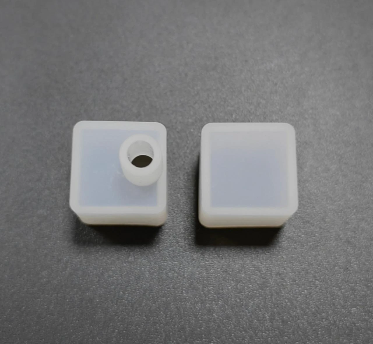
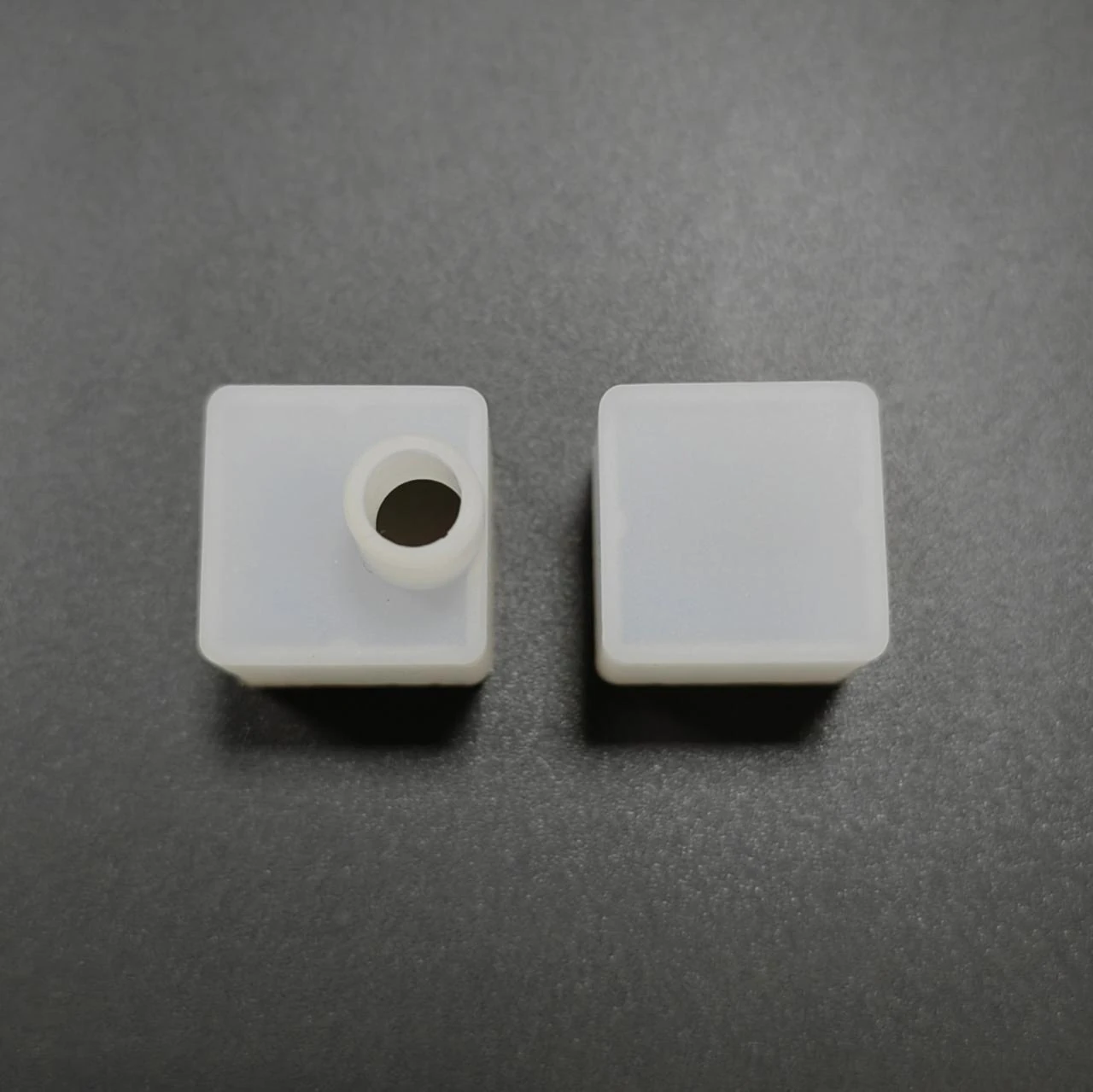
Ask whether the quoted configuration uses a factory-fitted lead, a model-specific field connector or a joined section. These are different assembly approaches. The correct method depends on the product construction and approved installation instructions. Accessories are available for selected products, but a photograph of an end cap is not proof that it fits every neon flex format.
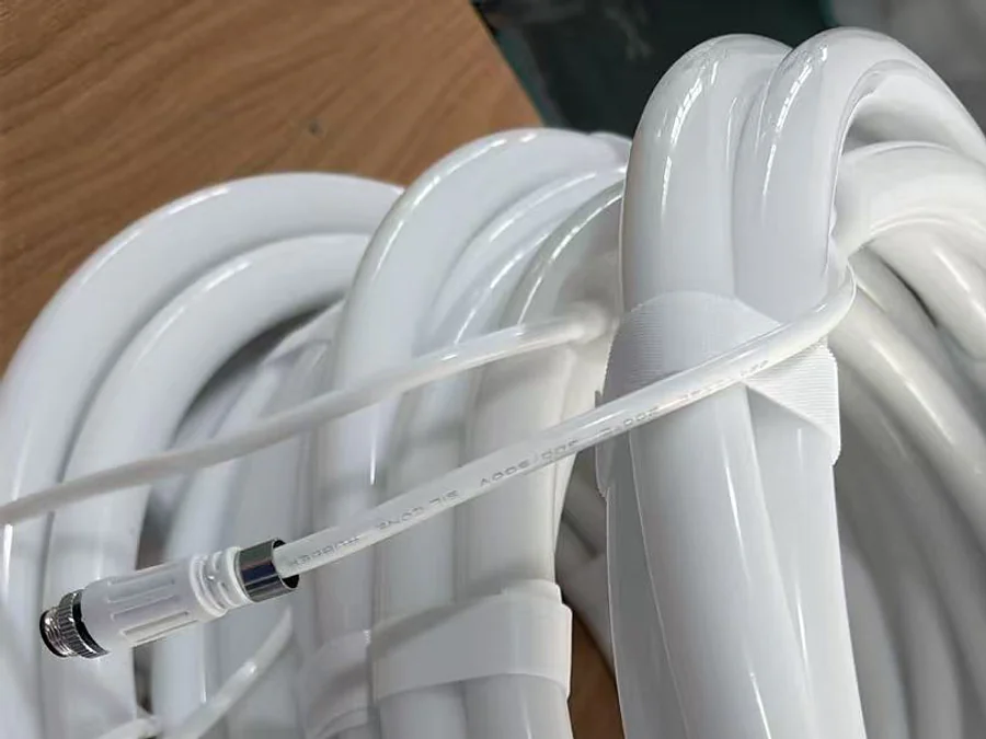
When reviewing a sample, compare the end both before and after the cable is positioned in the intended route. The end may be unobtrusive on a workbench but visible or difficult to accommodate once the mounting channel and surrounding finish are included.
Buying a separate silicone housing for your own strip? Use the silicone tube end cap guide to specify the mating section and cable exit. For a complete light, keep the proposed termination tied to the exact finished configuration.
4. Match the Electrical Arrangement, Not Just the Shape
The selected light’s supply and control requirements determine the conductor and connection arrangement. Identify the exact product data, the proposed power equipment and any controller before approving a connector. Do not assume that matching wire colours or a familiar-looking plug establishes electrical compatibility.
Show where power enters the run and where sections connect. For controlled or colour-changing products, include the controller and signal arrangement specified for the selected model. Keep connection details consistent from sample approval through the final order. Electrical installation should follow the exact product instructions and applicable local requirements.
If a separate LED strip will be inserted into a silicone tube, the LED strip connector types guide covers a different connection decision. The strip’s contact layout and board width matter there; they do not make a strip connector a finished neon flex end fitting.
5. Review the Complete End for Its Environment
State whether the installation is indoors, sheltered, exposed to rain or subject to cleaning water. Outdoor suitability cannot be inferred from the silicone body alone. The end treatment, cable entry, connection location, power equipment and mounting arrangement must be reviewed as a complete system for the quoted configuration.
Keep sensitive ends and joins away from places that collect water or cannot be inspected. Consider where runoff follows the cable and whether the route allows drainage. Do not claim an environmental rating for a loose connector or assume a field-made end inherits a rating from the uncut light body. For an exposed route, use the outdoor neon flex planning guide to review route and connection positions before final selection.
Even indoors, cleaning access, furniture movement and repeated handling can affect the cable exit. The aim is not to hide every end at any cost; it is to make the finished detail visually controlled, protected for its setting and practical to service.
6. Check One Complete End Assembly Before Repeating It
A useful sample includes the exact light, the proposed end fitting, a representative cable exit and the mounting detail. Inspect the unlit construction first: the end should sit as intended, the cable should not be pinched and the assembly should fit the available space. Then test the light with the specified equipment and review the visible transition from the normal viewing position.
Document the approved orientation and end detail with a photograph or marked drawing. If either the product model, cable route or mounting method changes, review the connection again. A loose sample of a plug beside an unrelated light does not approve the installed assembly.
Cutting or resealing is model-specific. Do not cut a finished light just because another neon flex product is field-cuttable. Obtain the selected product’s instructions and confirm who is responsible for the final end treatment before work begins.
7. What to Send for a Connection Review
- Selected neon flex model or clear end photograph
- Overall route and section lengths
- Emitting face and bend direction
- Mounting detail and available end space
- Required cable exit direction and lead position
- Supply and control arrangement for the selected model
- Indoor, sheltered or exposed installation conditions
- Access to joins and power equipment
- Sample quantity and estimated order quantity
If the product is not yet selected, send the route and desired light appearance first. A recommendation can then be reviewed against the actual construction rather than a guessed connector shape.
Common Connection Mistakes
Ordering by Plug Appearance
Similar housings can conceal different contacts and assembly methods. Start with the exact light model and its approved accessories.
Leaving the Cable Exit Until Installation
The exit determines how much room is needed at a start, stop or corner. Mark it on the drawing before confirming section lengths.
Treating an End Cap as the Whole Protection System
Exposure affects the light body, end treatment, cable, connection and equipment together. Review the finished assembly.
Assuming Every Product Can Be Cut and Rejoined
Field work must follow the selected model’s instructions. A factory-fitted configuration may be the better route for a controlled end detail.
Frequently Asked Questions
Are LED neon flex connectors universal?
No. The section shape, contact arrangement, cable exit and approved assembly method can differ between products. Confirm compatibility with the selected model.
Can a connector be hidden inside a mounting channel?
Only if the channel has enough space and the completed connection remains suitable and accessible for the installation. Check a physical sample.
Does an end cap make neon flex suitable for outdoor use?
Not on its own. The complete quoted product, end treatment, connections and equipment must suit the exposure.
Can a finished neon flex length be cut on site?
That depends on the exact model and its approved cutting and resealing method. Do not cut before checking the product instructions.
What if the cable must exit at a corner?
Show the corner, bend plane, mounting space and cable route. A revised section length or transition may be needed rather than forcing the cable through the bend.
Can I order a replacement connector from a photograph alone?
A photograph can start identification, but confirm the product reference, section, contact arrangement and cable exit before ordering. Include dimensions and clear views of both mating parts. Send these with your accessory request; an end that looks similar is not evidence of mechanical, electrical or environmental compatibility.