
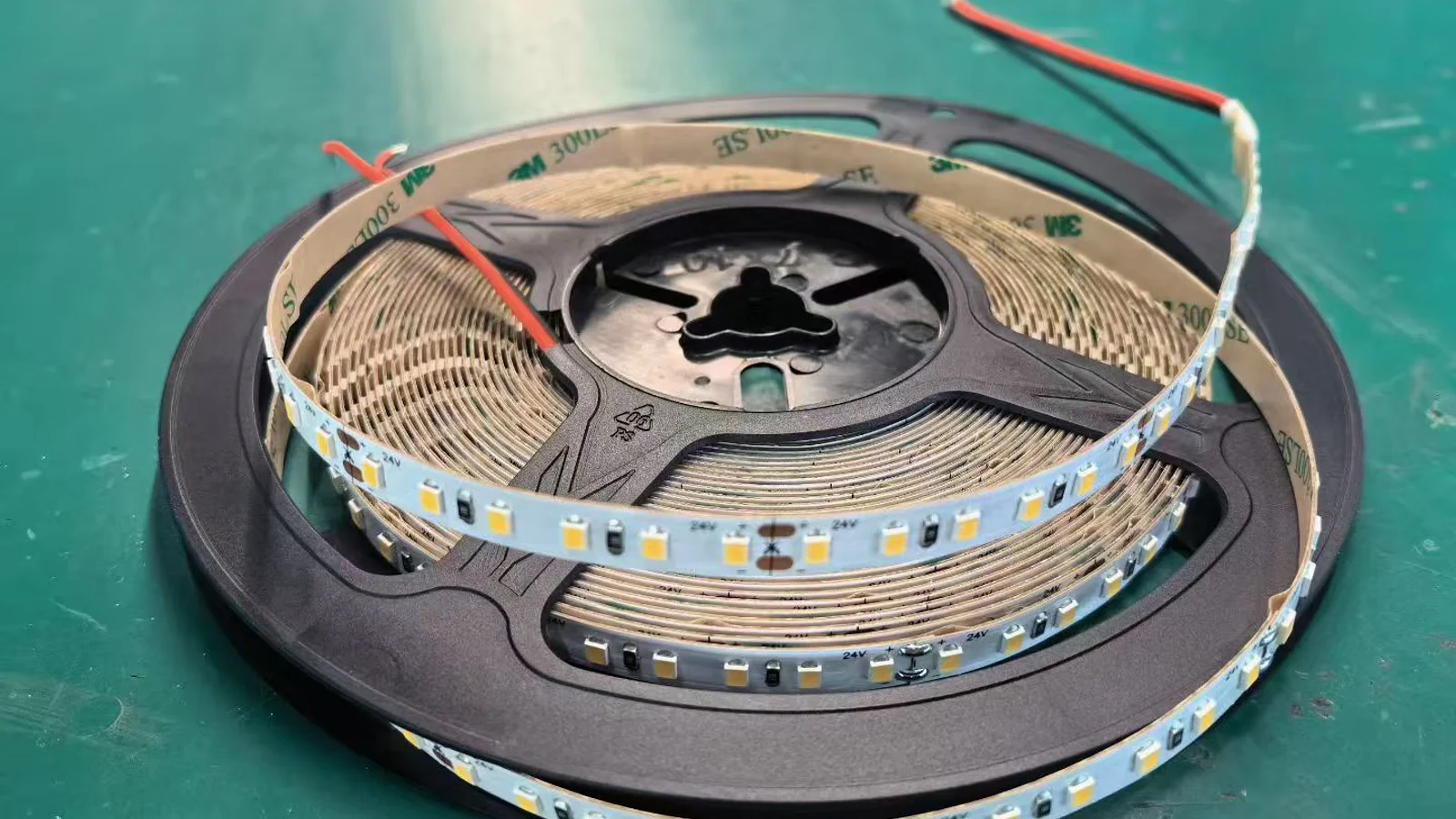
SMD LED strip types should be compared as complete strip constructions, not by package label alone. Start with the required light appearance, viewing distance and available installation space. Then review the selected strip’s package layout, LED spacing, board width, electrical data, cut arrangement and connection method against the profile, diffuser or enclosure that will hold it.
Choosing a package name is only the start of an AlisterTech strip-and-profile enquiry. The actual board width, component height and light spacing need to suit the silicone housing and viewing distance. If the strip is already selected, send its data sheet and dimensions. If it is still open, describe the installation and light appearance you need so the source and housing can be discussed together.
Short answer: An SMD package name identifies part of the LED construction, but it does not define the finished strip. Two strips using a similar package can differ in spacing, board layout, power arrangement, colour performance and visible result. Compare the exact strip model in the intended assembly.
Define the visible result and viewing position.
Review package arrangement, spacing and cut points.
Check board width, components and connections.
Use the exact model data and control plan.
1. What Does an SMD LED Package Label Tell You?
SMD means surface-mounted device. Package labels commonly identify the physical format of an individual LED package. That information can help when reviewing component size and board layout, but it does not by itself tell you how bright the finished strip will look, how much power it uses, how closely the LEDs are spaced or how the strip will perform inside a profile.
Treat the package label as an identification point, not a final selection rule. The strip data for the exact model should provide the electrical and optical information needed for evaluation. When comparing alternatives, keep the intended installation constant so the effect of package arrangement and spacing can be judged fairly.
SMD 5050 LED strip: check the complete strip, not just the package
When comparing an SMD 5050 LED strip, ask for the exact strip reference, board width, electrical data and a clear view of the cut-end contacts. The 5050 package label identifies the LED format; it does not establish the strip’s voltage, colour channels, LED spacing, brightness or connector fit.
SMD 2835 LED strip: compare layout and installation fit
An SMD 2835 LED strip can be offered in different board layouts and electrical configurations. Check the selected strip’s actual dimensions, component height, cut positions and intended light appearance. If you are replacing an existing strip, send its exact reference rather than assuming that the package code alone guarantees a fit.
SMD 3528 LED strip: request the model details
The same rule applies to an SMD 3528 LED strip: use the package code to start a comparison, then review the complete strip and its intended assembly. Do not substitute specifications from a different supplier or from another strip with the same package label.
For a current AlisterTech strip recommendation, send your required light colour, supply arrangement, available width, installation route and any reference strip. Explore SMD LED Strips.
2. Compare the Package and the Complete Strip Layout
Look beyond the individual LED. Review the board width, package orientation, component height, resistor or control-component placement, copper contact arrangement and cutting positions. These features affect how the strip fits, connects and follows a route. They can also affect where a soldered joint or connector sits within the available space.
A narrow lighting detail may have enough room for the board but not for a connector body or raised component. A bend near a cut point may place stress on the board or connection. Mark these constraints on the installation drawing before choosing the strip. The LED Strip Lights page provides the correct product-family starting point for model review.
3. LED Spacing, Viewing Distance and the Visible Light Line
The distance between visible LED packages influences how easily individual points can be seen, but spacing is only one part of the final result. The distance from the strip to the emitting surface, the diffuser or silicone geometry, the viewing angle and the surrounding brightness all contribute to the appearance.
A strip that looks even from across a room may show individual points at close range. A deeper profile or more diffusing material may smooth the line, but it can also change the amount and direction of visible light. Define where the light will be viewed and whether the source is direct, concealed or reflected before judging a sample.
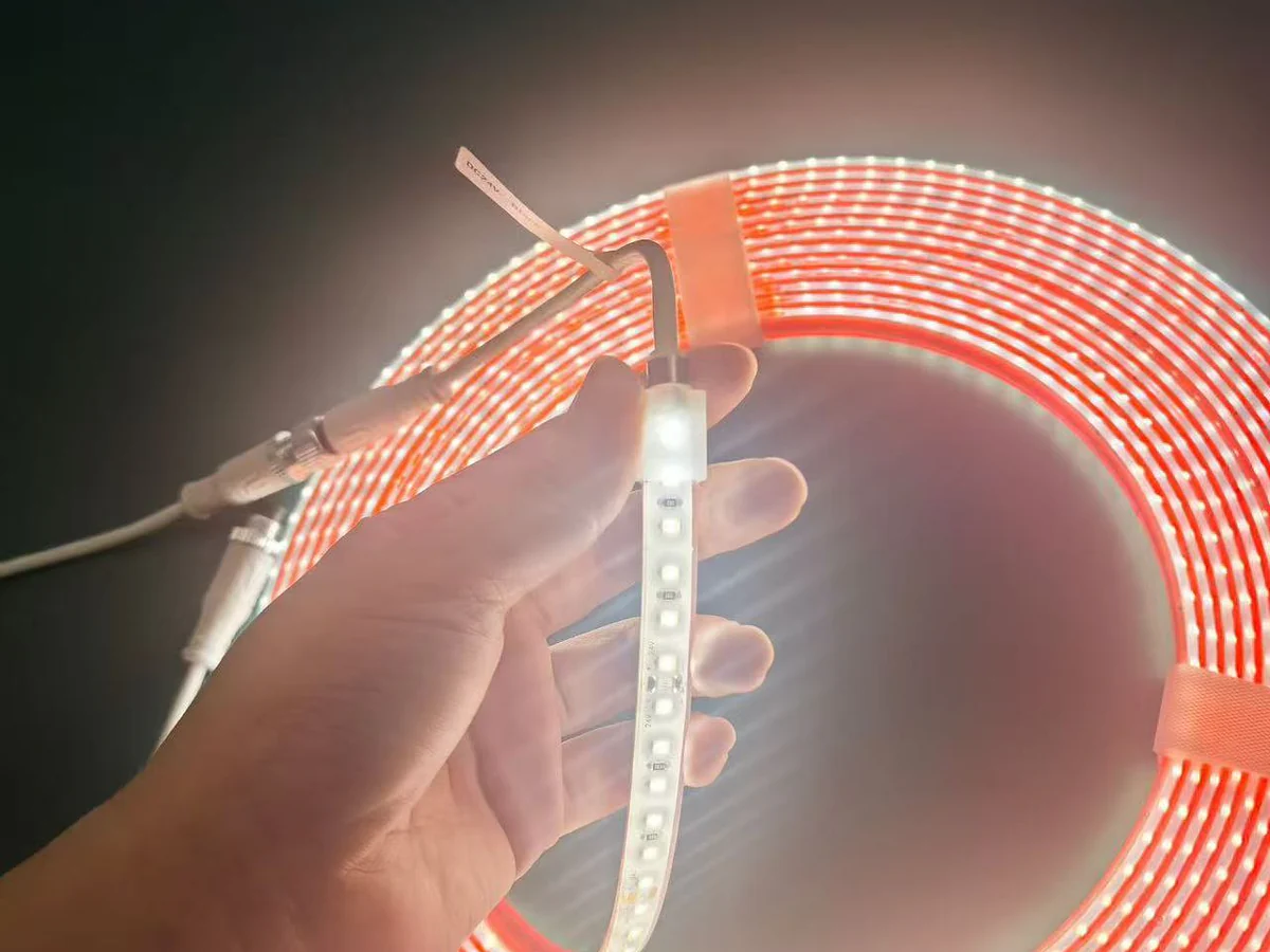
Use the LED strip diffusion guide to coordinate spacing, diffuser distance and the intended visible result. If the strip will sit inside silicone, also review the LED strip and silicone profile matching guide.
4. Match the Electrical Requirements to the Selected Model
Confirm the supply arrangement, control method and connection plan from the exact strip model. Do not transfer voltage, power or control assumptions from another strip because the packages look similar. The power supply and controller must be selected for the actual strip, installed length and operating arrangement.
Plan where power enters the run, where connections remain accessible and how cable exits are routed. Long or segmented installations may need a different connection plan from a short sample. Electrical work should follow the selected product documentation and applicable installation requirements.
5. Check the Strip Inside the Profile, Tube or Enclosure
Measure the usable internal space rather than relying on the outside size of a profile. Check board width, component height, solder joints, leads and any connector body that will enter the channel. Confirm how the strip is positioned and whether the emitting face points toward the intended surface.
The fit should be checked along straight runs, corners and transitions. A strip that fits loosely on a desk may shift inside a flexible profile, while a tight channel may interfere with components or make assembly difficult. Review the actual combination rather than assuming that nominal widths guarantee compatibility.
6. Compare Real Samples in the Intended Assembly
When appearance matters, compare samples under the same conditions. Use the intended profile or diffuser, viewing distance, mounting orientation and control setting. Photographing two strips in different exposure conditions can make the comparison misleading, so visual approval should be based on the installed sample.
Check both the unlit construction and the illuminated result. The unlit view shows board layout, component placement, cut points and connection access. The illuminated view shows visible spacing, colour appearance and whether the chosen diffuser creates the intended line.
7. What to Specify When Requesting an SMD Strip
- Required light colour and visible effect
- Viewing distance and normal viewing angle
- Available board width and component clearance
- Profile, tube, shelf or enclosure details
- Supply and control requirements
- Run lengths and connection locations
- Cut, cable and connector arrangement
- Indoor or outdoor installation conditions
- Sample requirement
- Estimated quantity
Common Selection Mistakes
Choosing Only by Package Number
The package number does not describe the complete strip or installed result. Compare exact model data and a representative sample.
Ignoring Connections and Cut Points
The board may fit while a connector, solder joint or cable exit does not. Include these details in the available space.
Judging Diffusion From a Bare Strip
A bare-strip photograph cannot show the final appearance inside a profile or behind a diffuser. Review the complete assembly.
Using Data From a Similar Strip
Electrical and optical information should come from the selected model. Similar appearance does not establish identical operating requirements.
Frequently Asked Questions
Is one SMD package type always brighter than another?
No. Finished output depends on the exact LED, drive conditions, spacing and strip construction. Use model-specific data rather than package size as a brightness shortcut.
Does closer LED spacing always create a seamless line?
Closer spacing can help, but diffuser distance, material, profile geometry and viewing position also matter. Test the complete assembly.
Can an SMD strip be installed in a silicone tube?
It can be considered when the board, components, light direction, bend route and assembly method match the tube. Compatibility should be checked with the actual strip and profile.
Should COB or SMD be used for a visible light line?
Both may be evaluated. The right choice depends on appearance, space, control and assembly requirements. See the COB versus SMD comparison for the main differences.
What is the best first sample?
Use the selected strip inside the intended profile or diffuser at the real viewing distance. Include a representative connection and any critical corner or transition.