Coves & ceiling lines
Confirm the installation detail with the selected configuration.
View application
AL-HR11-B243012022 references the 12 x 12 mm profile pictured on catalogue page 12, profile 2. Compare its listed LED configurations, then confirm the exact light colour, electrical arrangement and connections for your installation.
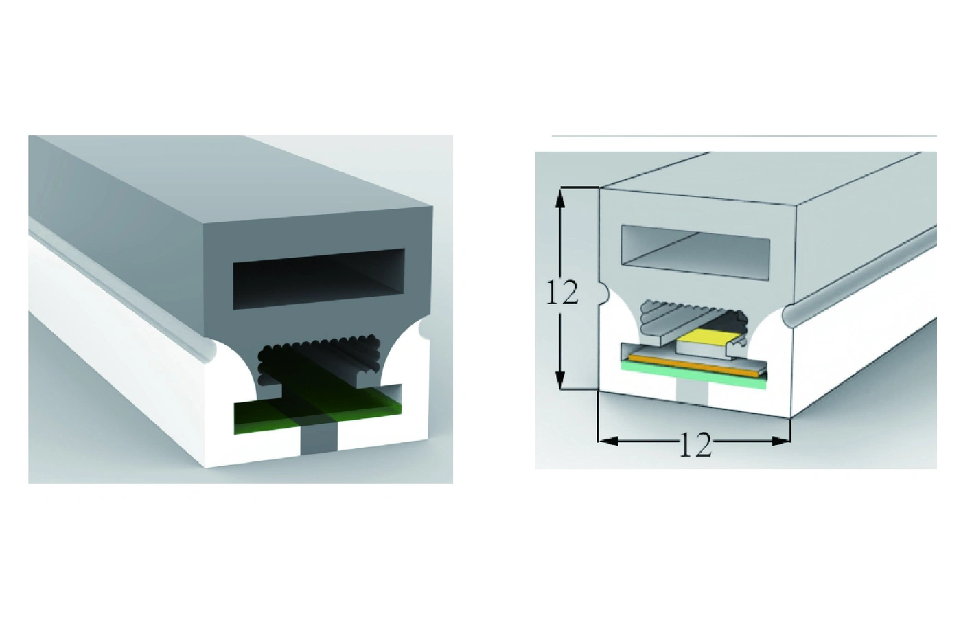
AL-HR11-B243012022 is an AlisterTech reference for the 12 x 12 mm top-emitting led neon flex profile shown in the International Catalogue. The page groups the configuration rows pictured under profile 2 on page 12; each retains its own full AlisterTech configuration code. The top-emitting geometry is a starting point for upward-facing linear light. Choose the exact row rather than applying one voltage, power or cut length to every variant.
| Reference | Profile detail |
|---|---|
| AlisterTech reference | AL-HR11-B243012022 |
| Catalogue source | HR11-B243012022 |
| Profile family | Top-Emitting LED Neon Flex |
| Profile size | 12 x 12 mm |
The reference uses the full catalogue code, not a code derived from profile dimensions.
For RGB LED neon flex in this profile, AL-HR11-B24RGB12022 is the listed 24 V RGB configuration. AL-HR11-B24RGB10222-2811 is the separate 12 V Pixel RGB configuration with WS2811 SMD2835. These are different electrical and control arrangements, not two supply settings for one product. Use the exact row below when selecting the power supply, cutting interval and connection method.
For a Pixel RGB enquiry, send the intended lighting effect, controller reference, installation route and power-feed locations. Controller compatibility and the planned controlled sections must be reviewed for the selected assembly; the configuration name alone does not specify your complete control system.
Each line below is a separate listed LED configuration of the pictured mechanical profile. Include the full configuration code in your enquiry.
| AlisterTech configuration | LED type | LEDs/m | Colour | CRI | Cut length | lm/m | PCB | Voltage | W/m | Finished size (mm) | IP |
|---|---|---|---|---|---|---|---|---|---|---|---|
| AL-HR11-B243012022 | SMD2835 | 120 | White / Red / Blue Green / Yellow | >80/90 | 50mm | 700 | 8mm | DC24V | 12 | 5000*12*12 | IP67 |
| AL-HR11-B24RGB12022 | SMD3838 | 120 | RGB | / | 50mm | 330 | 8mm | DC24V | 14.4 | 5000*12*12 | IP67 |
| AL-HR11-B24RGB10222-2811 | WS2811 SMD2835 | 102 | Pixel RGB | / | 29.4mm | 660 | 8mm | DC12V | 24 | 5000*12*12 | IP67 |
Specifications vary by LED configuration and model. Confirm the final quoted configuration and current technical documentation before ordering. A slash is reproduced where the catalogue does not give a CRI value. The * notation and finished-size values are retained as printed; do not treat the first size value as a maximum single-feed length.
IP67 is listed for these catalogue configurations. Confirm the complete quoted assembly, cable exits and end treatment for the intended exposure; the table is not a separate test report or certification.
Start with the visible aperture and available width and depth. Position the upward-facing emitting surface toward the intended view or reflected surface. After selecting the profile geometry, compare the individual LED configuration: light colour, density, CRI, cut length, PCB width, voltage, power and finished assembly rating. Review the strip, profile, end treatment and mounting together. A top-emitting face does not, on its own, establish a bending plane or minimum bend radius.
Confirm the installation detail with the selected configuration.
View applicationConfirm the installation detail with the selected configuration.
View applicationConfirm the installation detail with the selected configuration.
View applicationAccessory compatibility should be confirmed against the selected profile before quotation. Matching dimensions alone do not establish the correct end cap, cable exit or mounting fit.
Use the exact profile and configuration when discussing your project. The International Catalogue contains the complete model rows; accessory documents support a separate fit review.
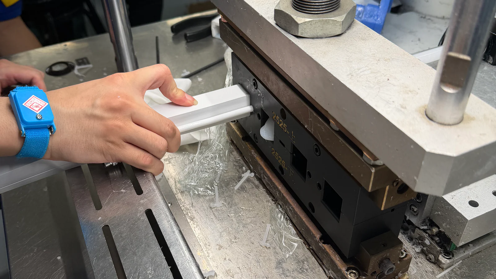
Start with a catalogue profile when its section fits. If the groove, emitting face, strip space or end interface needs a different geometry, send a drawing, installation sketch or physical sample for custom silicone extrusion review.
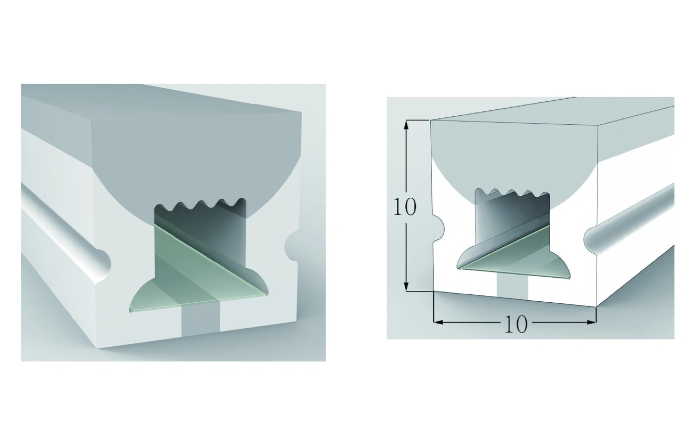
10 x 10 mm · Top-Emitting LED Neon Flex
3 catalogue configurations
View profile & configurations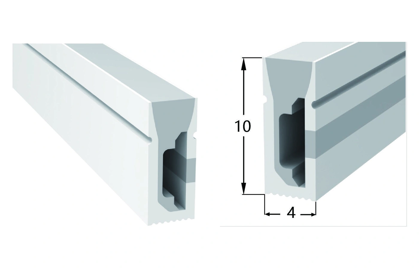
4 x 10 mm · Side-Emitting LED Neon Flex
3 catalogue configurations
View profile & configurations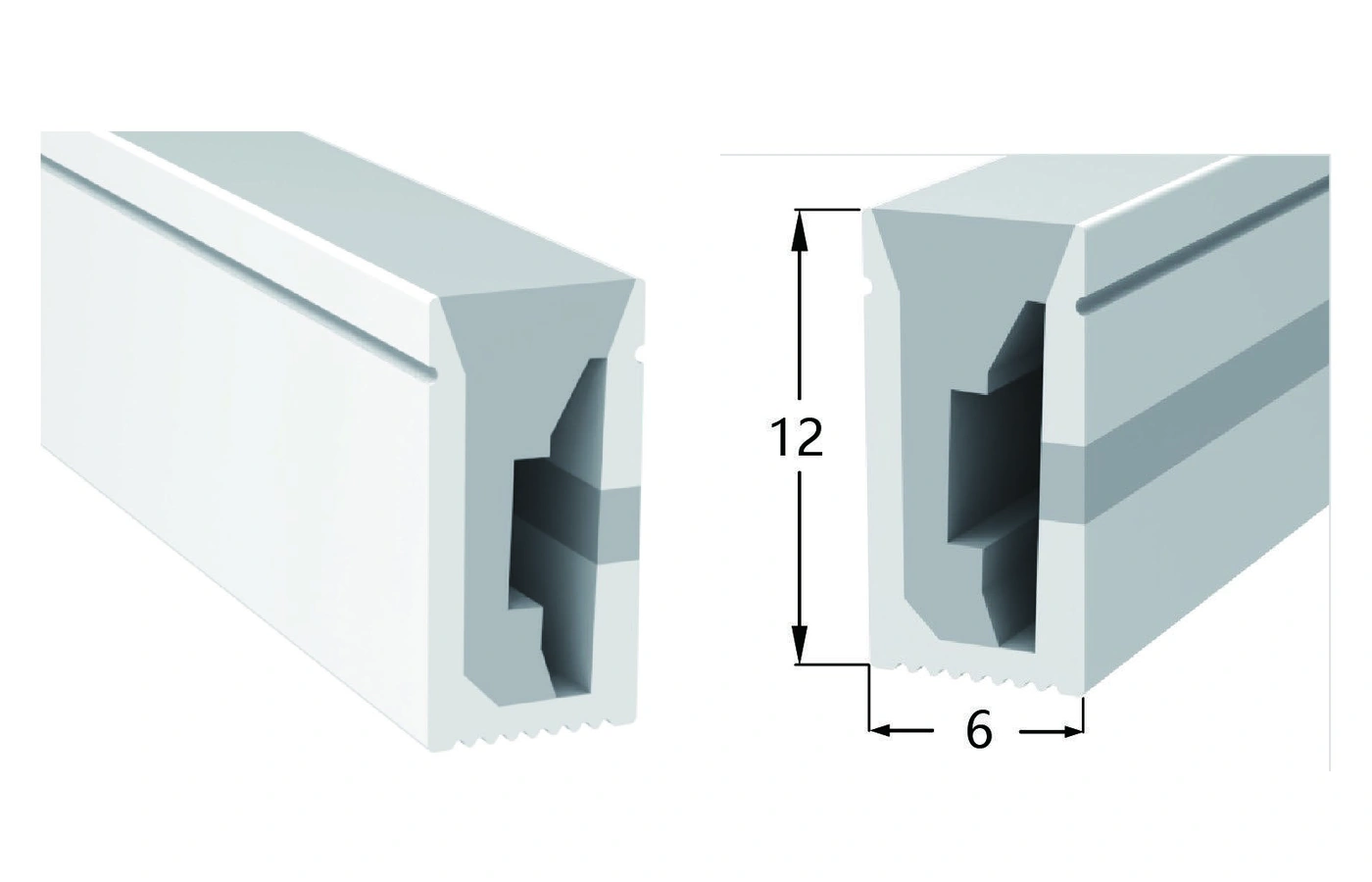
6 x 12 mm · Side-Emitting LED Neon Flex
3 catalogue configurations
View profile & configurations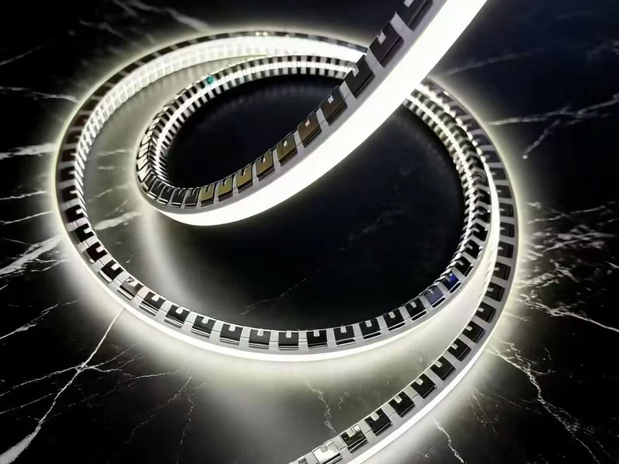
Send the exact configuration code, section drawing, light appearance and quantity. Include mounting and cable-exit requirements so the complete quotation can be reviewed.