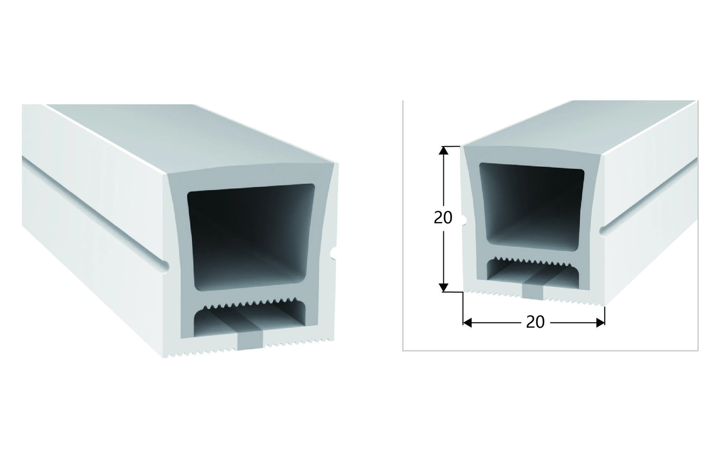
AL-HR11-B243012030
Compare three light-source configurations and mounting details.
View Profile & Specifications
AL-HR11-B243012028 offers the 20 x 14 mm section shown below. Select the light colour and exact electrical configuration, then match the mounting route and cable exits to your installation.
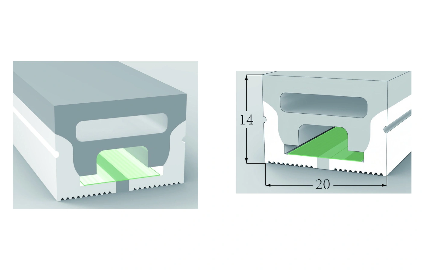
Position the upward-facing light surface within your recess or visible line. Mark the opening and mounting depth so the selected section and end connections can be checked together.
Allow for the LED board, mounting support, cable exit and end treatment, not only the outside size. Emitting direction does not establish a permitted bending plane or minimum bend radius.
Choose the exact AL-HR11-B243012028 configuration for your quote. Voltage, light source, output and cutting interval are row-specific.
All three listed 20 x 14 mm configurations use DC24V and a 12 mm PCB reference. Single-colour and RGB options have a 50 mm cutting interval; the WS2811 Pixel RGB option has a 55.6 mm interval and its own power and controller requirements.
| Configuration | LED type | LEDs/m | Colour / CCT | CRI | Cut length | lm/m | PCB | Voltage | W/m | Finished size (mm) | IP |
|---|---|---|---|---|---|---|---|---|---|---|---|
| AL-HR11-B243012028 | SMD2835 | 120 | White / Red / Blue Green / Yellow | >80/90 | 50mm | 710 | 12mm | DC24V | 14 | 5000*20*14 | IP67 |
| AL-HR11-B24RGB12028 | SMD3838 | 120 | RGB | / | 50mm | 310 | 12mm | DC24V | 14.4 | 5000*20*14 | IP67 |
| AL-HR11-B24RGB10828-2811 | WS2811 SMD2835 | 108 | Pixel RGB | / | 55.6mm | 630 | 12mm | DC24V | 24 | 5000*20*14 | IP67 |
CRI values and * notation are retained as printed. A slash means no CRI value is supplied for that row. Finished size is not a guaranteed maximum single-feed length; confirm feeds, finished lengths and controls for your project.
Technical reference: International Catalogue page 12, profile 6. Download the source specifications
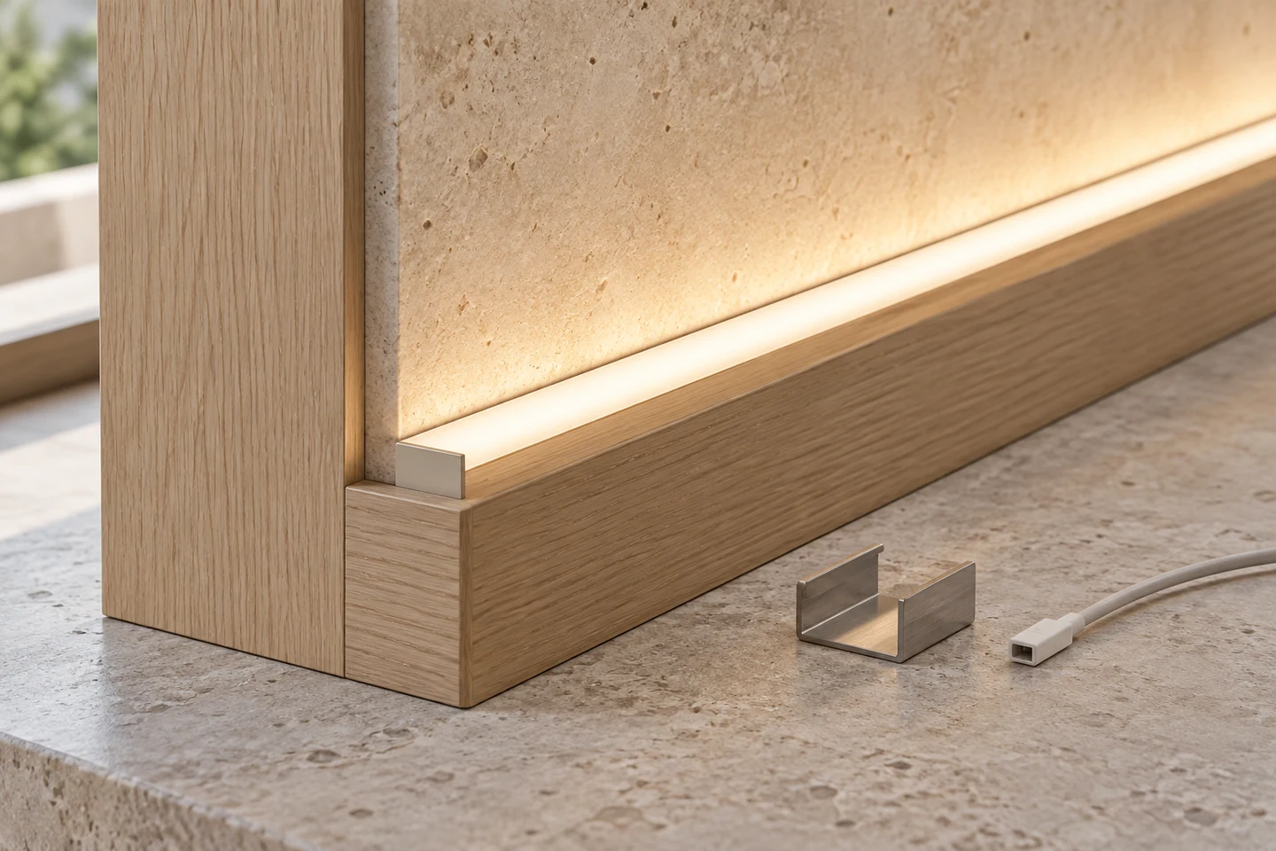
Show the mounting surface, available width and depth, corners and connection space. A similarly sized cap or bracket is not automatically compatible.
Review accessoriesIdentify cable exit, end treatment, supply and controller positions. Select colour control separately from mechanical shape and approve the light line from the intended view.
Technical documents
Position the upward-facing light surface within your recess or visible line. Mark the opening and mounting depth so the selected section and end connections can be checked together.
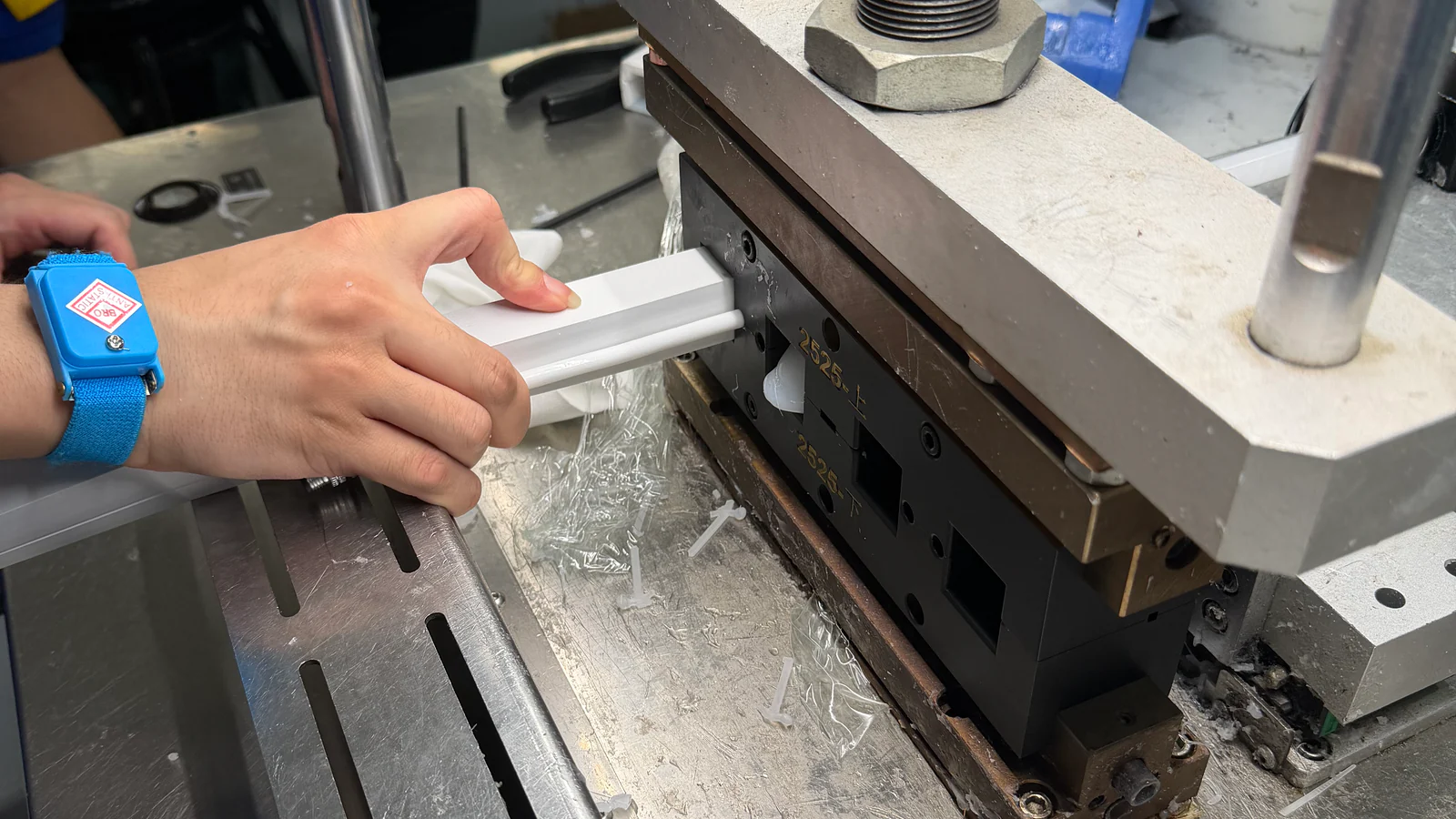
Start with this profile when its section fits. If the groove, light face or internal clearance must change, send a drawing or sample for custom silicone extrusion. Include segment lengths, colour or animation, connection requirements and quantity.
Review fit, light appearance and connections on a sample before agreeing production.
Send the full AL-HR11-B243012028 profile reference together with the exact configuration code from the table. The three rows have separate light-source and electrical requirements.
Use the voltage and power of the selected row. The listed rows use DC24V, but load and control still depend on the chosen configuration.
Provide the groove or support dimensions, curve route, cable direction and end space. Match caps and retention parts to the actual section before ordering.
The listed configurations carry IP67 in the catalogue. Confirm the complete quoted assembly, terminations and exposure. This does not establish suitability for immersion beyond the specified conditions, cleaning jets or every outdoor environment.
Send a drawing, required lengths, light appearance, controller and quantity. Review a sample for geometry, light effect and connections before agreeing the production configuration.
Compare three light-source configurations and mounting details.
View Profile & Specifications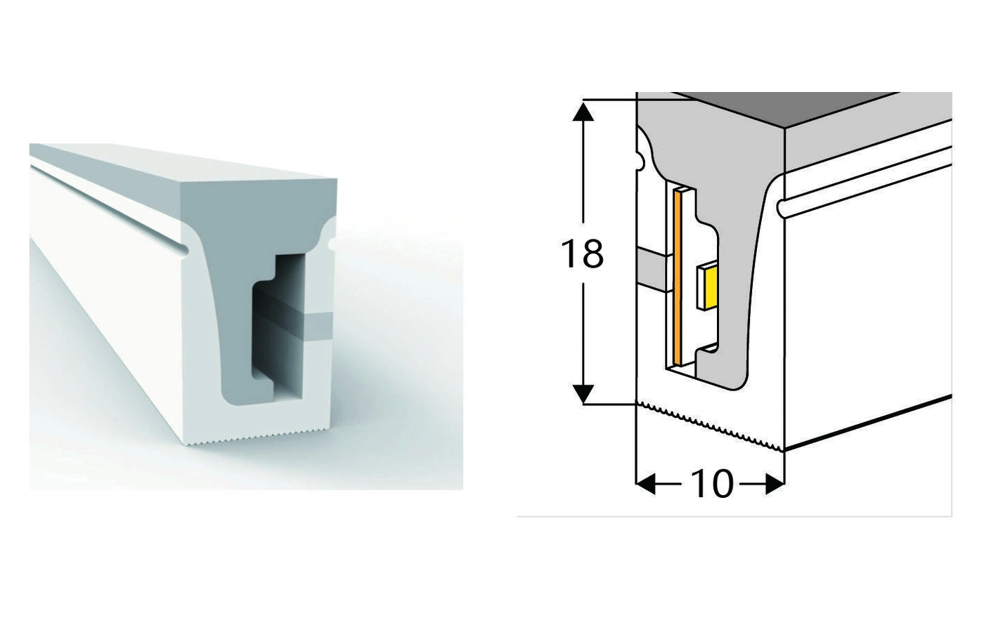
Compare three light-source configurations and mounting details.
View Profile & SpecificationsSend the selected configuration, route drawing, lengths, mounting details and quantity for a matched quote.